AI technical title is built by Patsnap AI team. It summarizes the technical point description of the patent document.
a heart rate monitor and eyeglasses technology, applied in the field of eyeglasses with heart rate monitors, can solve the problems of unsatisfactory approach and inconvenient approach
Active Publication Date: 2010-03-16
INGENIOSPEC
View PDF205 Cites 314 Cited by
Summary
Abstract
Description
Claims
Application Information
AI Technical Summary
This helps you quickly interpret patents by identifying the three key elements:
Problems solved by technology
Method used
Benefits of technology
Benefits of technology
[0008]In one embodiment, the present invention provides a heart rate sensor attached to, integral with or tethered to a pair of glasses. When worn, the pair of glasses is in a stable position relative to the user. The glasses serve as a good platform for heart rate sensing.
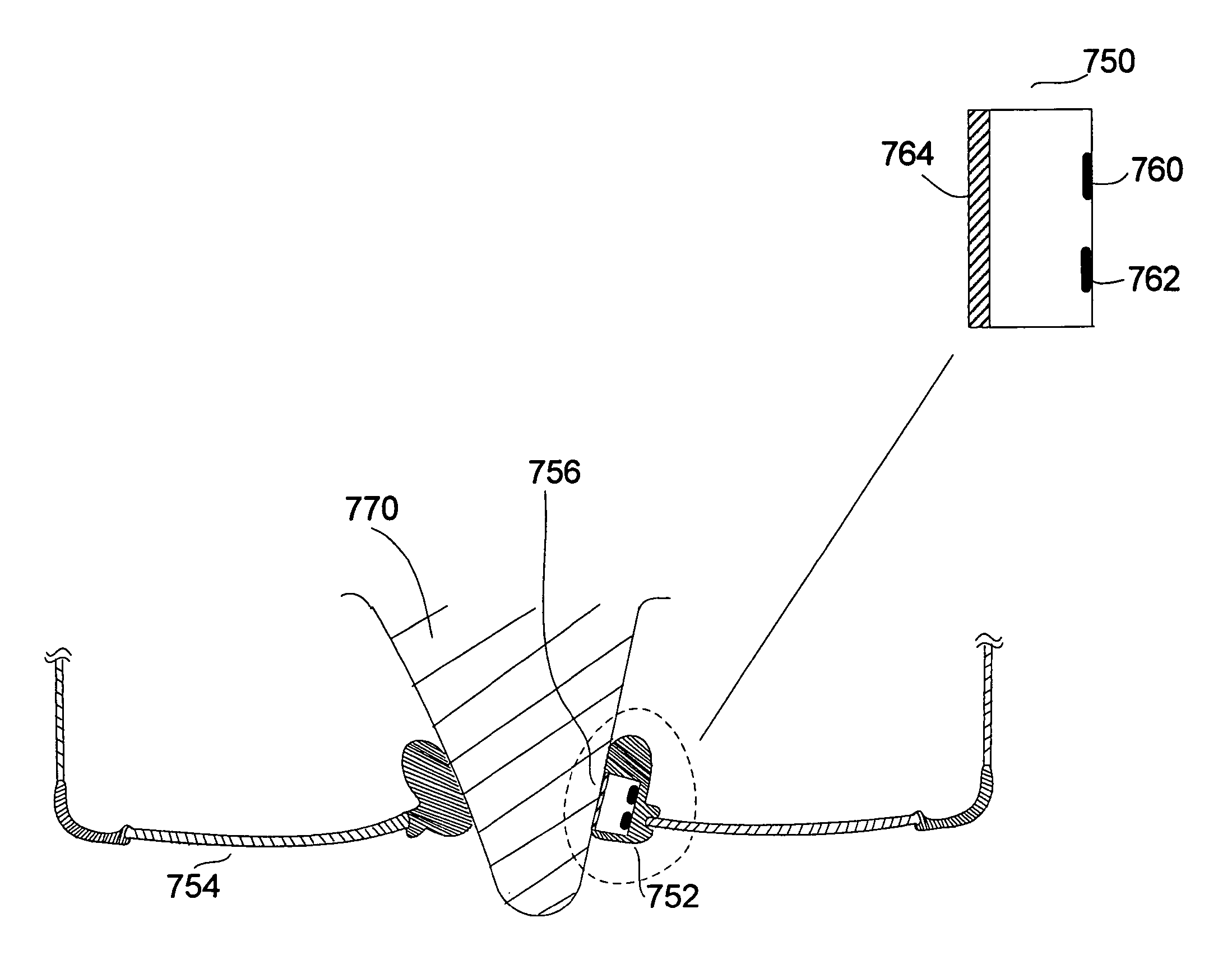
[0009]In one embodiment, the sensor can be an infrared transmitter with an infrared detector on a clip. The clip could be tethered to a temple of the glasses. The user can attach the clip to her ear lobe to measure her heart rate. With the ear lobe being adjacent to the glasses, the length of the wire tethering the clip to the temple could be relatively short. A short wire is more convenient for the user than a long wire, particularly if the user has to move around. Also, the degree of movement of the clip relative to the ear lobe typically is less if the wire is short, which could lead to more accurate measurements.
[0010]In another embodiment, instead of a wire, the clip could be electrically coupled to the glasses through an adjustable mechanical arm, or a semi-rigid arm or cable. The mechanical arm or semi-rigid arm or cable could enhance the stability of the clip relative to the glasses.
[0017]In one embodiment, the glasses further include at least a portion of other electronic devices, such as a pedometer or a temperature sensor. The outputs from the different devices could be combined to help the user. For example, if the user constantly experiences irregular heart beat, the pedometer with the heart rate monitor would be able to better indicate if the user has been active or at rest at the onset of an irregular heart beat.
Problems solved by technology
This approach can be quite inconvenient because the person has to wear a band across his chest in order to get the necessary measurements.
This approach is unsatisfactory if one intends to remain active, or to use one's hands while measurements are taken.
Method used
Image
Click on the blue label to locate the original text in one second.
Reading with bidirectional positioning of images and text.
Examples
Embodiment Construction
[0029]In one embodiment, a pair of glasses for a user has a heart rate (heart beat) monitor. The heart rate monitor can be partially or fully embedded in the eyeglasses. For example, the heart rate monitor can be substantially embedded in a temple of the eyeglasses. In another embodiment, the heart rate monitor can be coupled (either permanently or temporarily) to the eyeglasses.
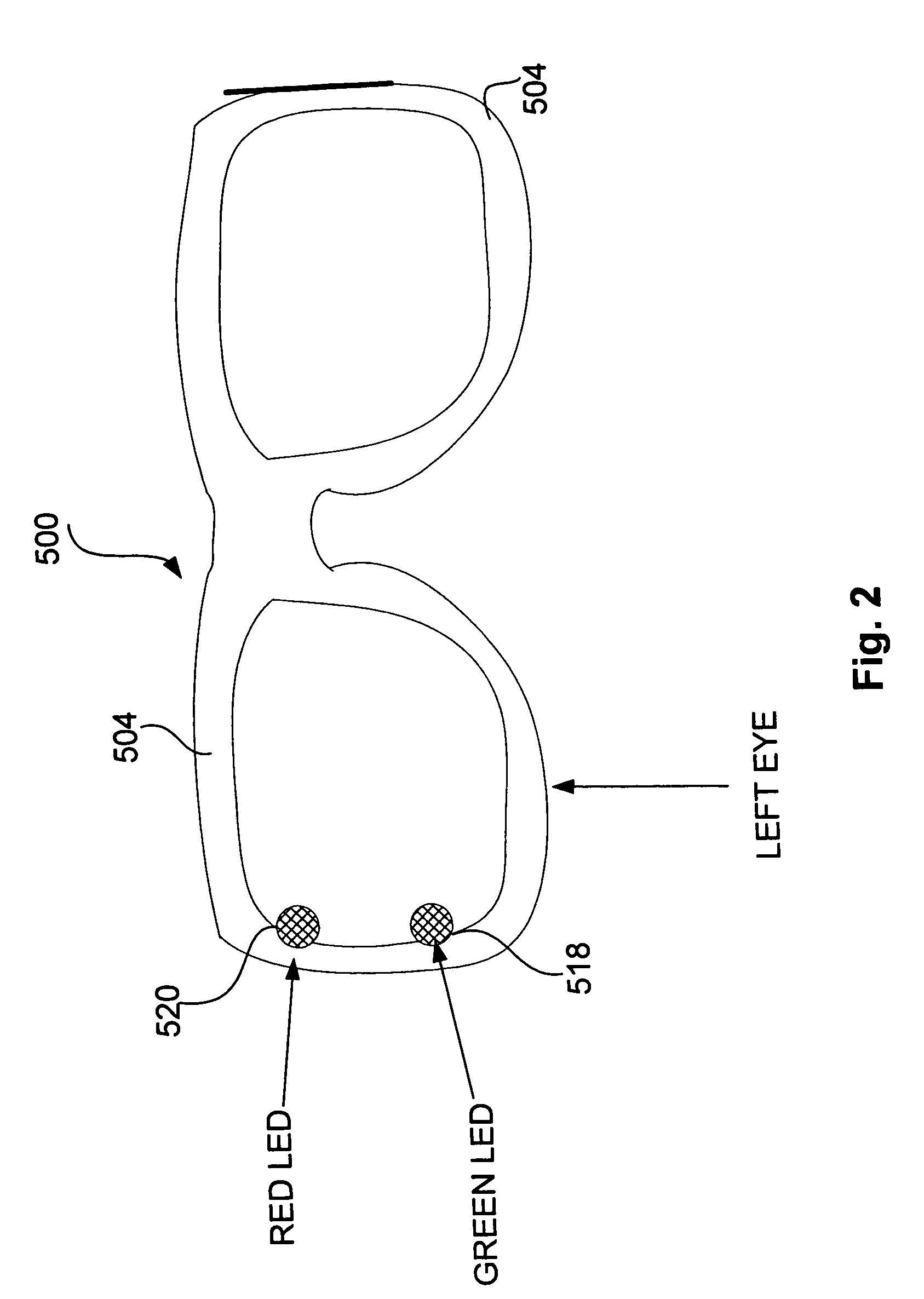
[0030]In one embodiment, the heart rate monitor can include an infrared sensor (or IR sensor) and processing circuitry. Using measurements from the infrared sensor, the processing circuitry can determine the user's heart rate. The eyeglasses can also include one or more output devices, such as a speaker or beeper, for audio output, and / or a display for visual output.
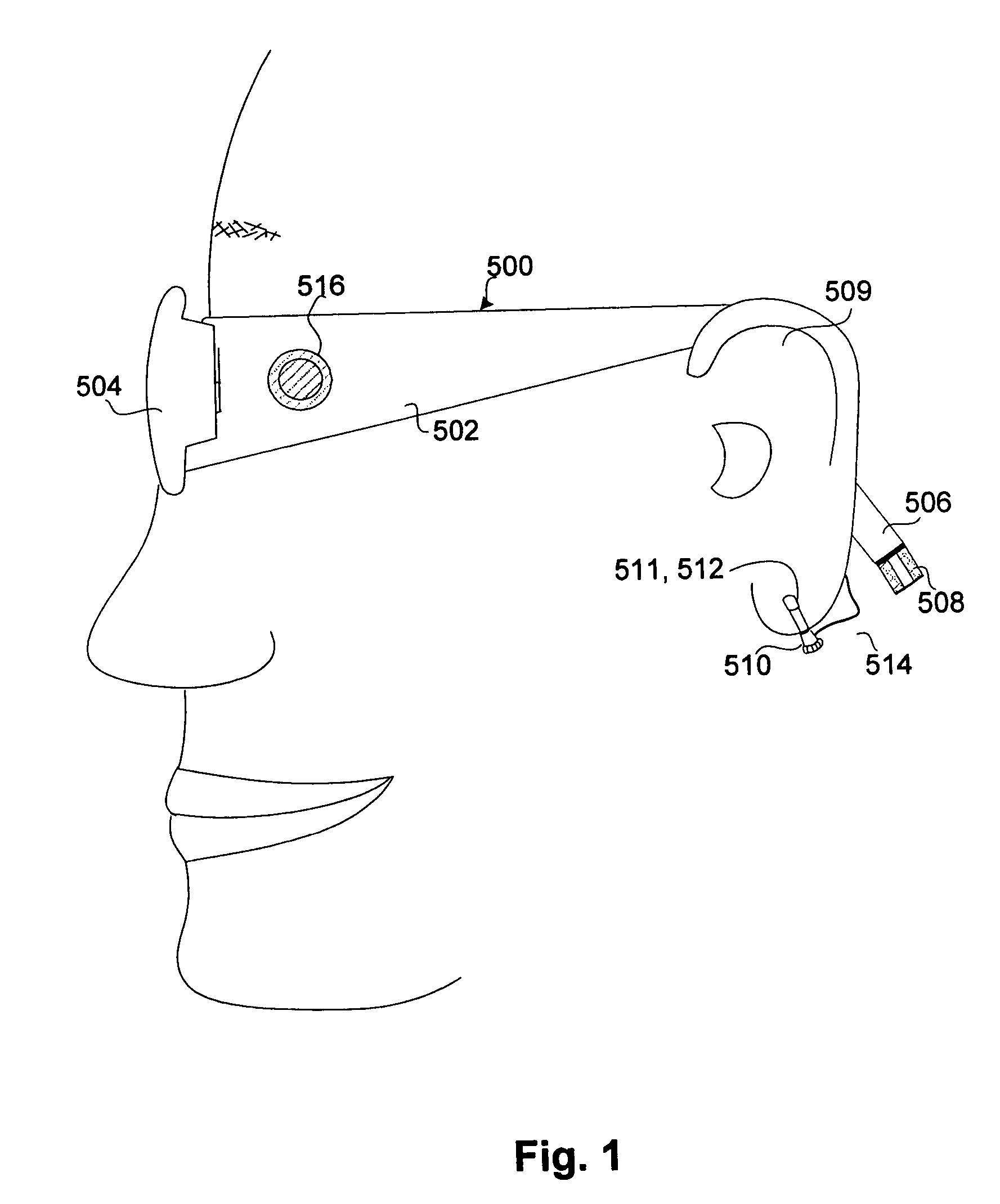
[0031]FIG. 1 illustrates a pair of eyeglasses 500 having heart rate monitoring capabilities according to one embodiment. The pair of eyeglasses 500 includes left and right temples 502 and left and right lens holders 504.
[0032]A rearward temple po...
PUM
Abstract
A pair of glasses with a heart-rate monitor according to one embodiment. The heart-rate monitor is configured to measure the heart rate of the user of the glasses. The heart-rate monitor can include a sensor with a radiation transmitter and a radiation receiver. The radiation could be infrared radiation. In one approach, the receiver measures signals transmitted by the transmitter through a body part of the user to measure the user's heart rate. The sensor could be incorporated in a clip to clip onto the body part of the user, such as the ear lobe of the user. In another approach, the receiver measures signals transmitted by the transmitter and reflected by a body part of the user to measure the user's heart rate.
Description
CROSS-REFERENCE TO RELATED APPLICATIONS[0001]This application is related to U.S. patent application Ser. No. 11 / 183,256, filed Jul. 15, 2005, and entitled “EYEGLASSES WITH ELECTRICAL COMPONENTS,” which is hereby incorporated herein by reference, which in turn is a continuation-in-part of U.S. patent application Ser. No. 10 / 964,011, filed Oct. 12, 2004, and entitled “TETHERED ELECTRICAL COMPONENTS FOR EYEGLASSES,” which is hereby incorporated herein by reference, which in turn claims priority to each of: (i) U.S. Provisional Patent Application No. 60 / 509,631, filed Oct. 9, 2003, and entitled “TETHERED ELECTRICAL COMPONENTS FOR EYEGLASSES,” which is hereby incorporated herein by reference; (ii) U.S. Provisional Patent Application No. 60 / 527,565, filed Dec. 6, 2003, and entitled “ADAPTABLE COMMUNICATION TECHNIQUES FOR ELECTRONIC DEVICES,” which is hereby incorporated herein by reference; (iii) U.S. Provisional Patent Application No. 60 / 562,798, filed Apr. 15, 2004, entitled “EYEWEAR WI...
Claims
Application Information
Patent Timeline
Application Date:The date an application was filed.
Publication Date:The date a patent or application was officially published.
First Publication Date:The earliest publication date of a patent with the same application number.
Issue Date:Publication date of the patent grant document.
PCT Entry Date:The Entry date of PCT National Phase.
Estimated Expiry Date:The statutory expiry date of a patent right according to the Patent Law, and it is the longest term of protection that the patent right can achieve without the termination of the patent right due to other reasons(Term extension factor has been taken into account ).
Invalid Date:Actual expiry date is based on effective date or publication date of legal transaction data of invalid patent.

