Flue smoke exhaust system and control method thereof

A smoke exhaust system and flue technology, which is applied in the combustion method, heating method, and oil fume removal, etc., can solve the problems of changing the angle of the valve plate, reducing the smoke exhaust ability of the range hood, and affecting the opening of the valve plate.

Active Publication Date: 2020-06-23
NINGBO FOTILE KITCHEN WARE CO LTD
View PDF5 Cites 1 Cited by
  • Summary
  • Abstract
  • Description
  • Claims
  • Application Information

AI Technical Summary

Problems solved by technology

[0003] There are many range hoods that are turned on at the same time for high-rise public flues, which is likely to cause flow fluctuations. Generally, the valve plate of the fire damper opens with the air flow when the user is turned on, and has a longer life than the electric valve body and is more durable. However, the valve plate of this fire damper Because it is opened by the airflow, it can only be maintained at a relatively large opening angle, and the slight fluctuation of the airflow can easily cause the angle of the valve plate to change
In addition, in the case of high flue back pressure, the valve plate may not open properly, which seriously affects the opening of the valve plate, thereby reducing the smoke exhaust capacity of the range hood

Method used


Image

  • Flue smoke exhaust system and control method thereof
  • Flue smoke exhaust system and control method thereof
  • Flue smoke exhaust system and control method thereof

Examples


Embodiment Construction

[0031] The present invention will be further described in detail below in conjunction with the accompanying drawings and embodiments.

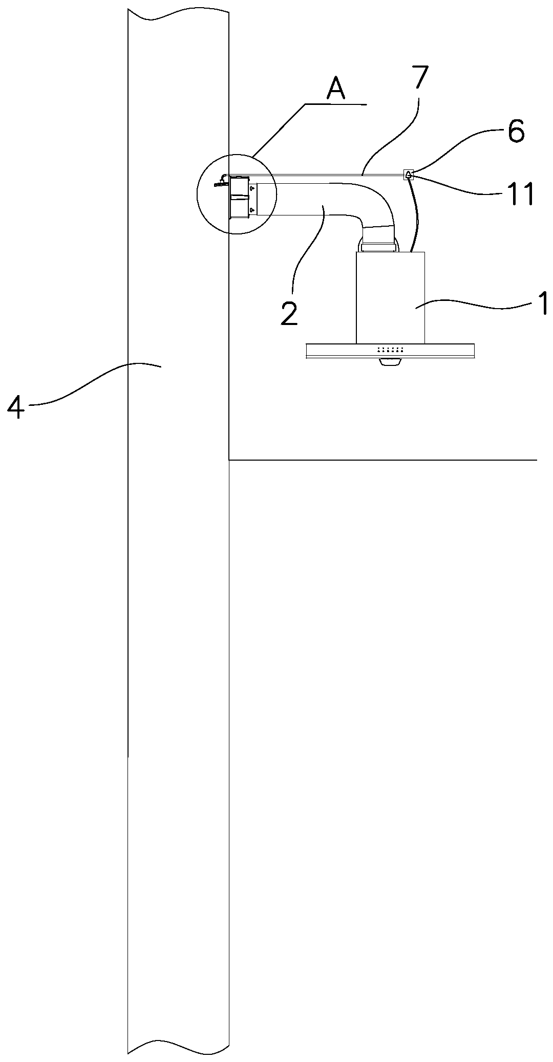
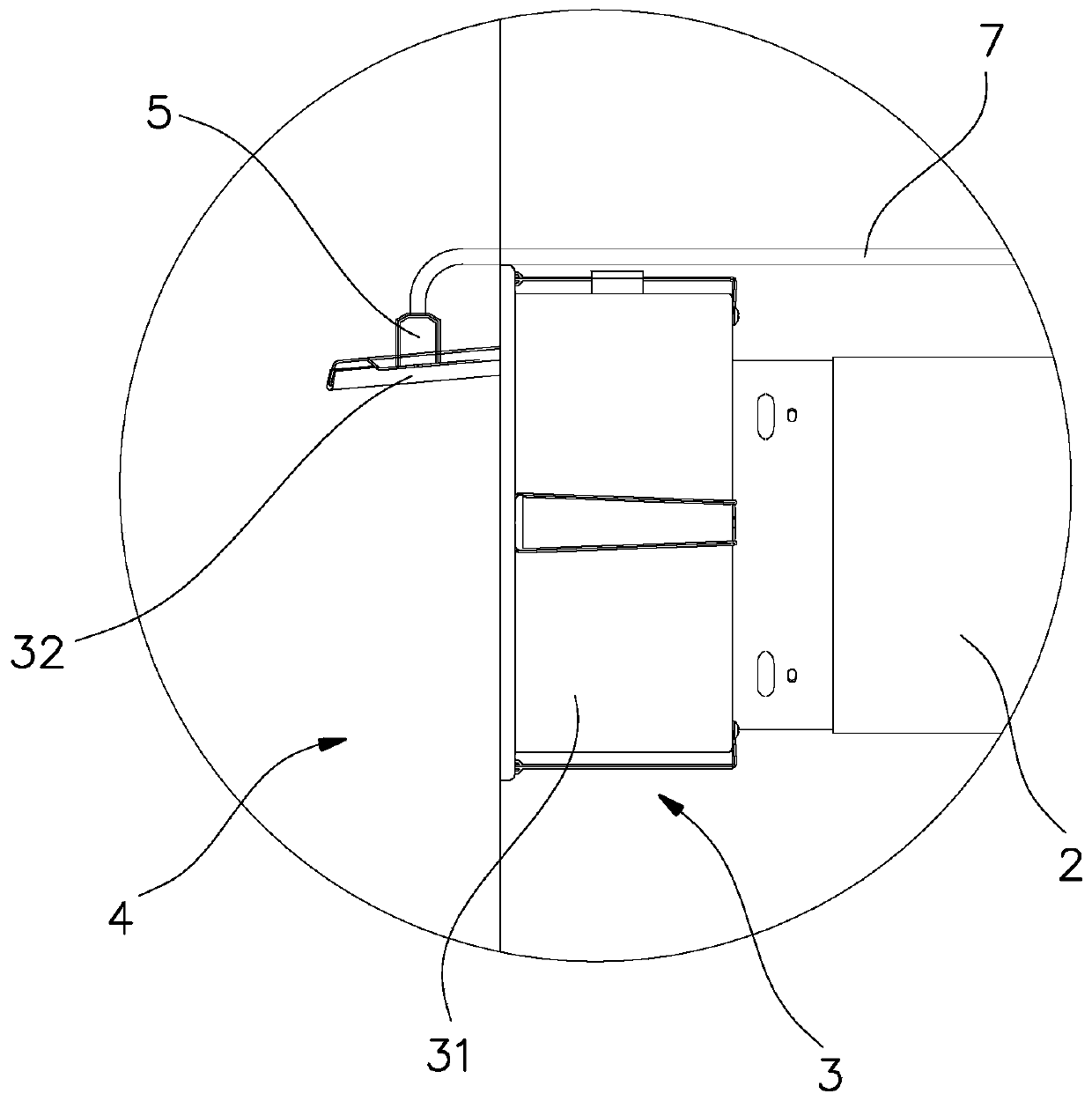
[0032] Such as figure 1 with figure 2 As shown, the flue smoke exhaust system of this embodiment includes a range hood 1 , a smoke pipe 2 , a fire damper 3 , a public flue 4 , an electromagnetic chuck 5 and a power detection socket 6 .

[0033] Among them, the fire damper 3 includes a valve body 31 and a valve plate 32, the valve body 31 is installed on the outlet end of the smoke pipe 2, the valve plate 32 is installed on the valve body 31, and the air outlet of the range hood 1 passes through the smoke pipe 2 and the fire damper in turn. 3 communicates with public flue 4. When the range hood 1 is working, the oil fume generated is discharged into the public flue 4 through the smoke pipe 2 and the fire damper 3 . The above-mentioned structure is the same as the existing flue exhaust system, and will not be described here.

[0034] In thi...


PUM


Abstract

The invention disclsoes a flue smoke exhaust system. The flue smoke exhaust system comprises a public flue, a range hood, a smoke pipe and a fireproof valve, an air outlet of the range hood communicates with the public flue through the smoke pipe and the fireproof valve, and the fireproof valve comprises a valve body installed at the outlet end of the smoke pipe and a valve plate installed on thevalve body; and the flue smoke exhaust system is characterized by further comprising an electromagnetic chuck and a power detection socket, wherein the electromagnetic chuck is used for sucking the valve plate at the maximum opening angle, the electromagnetic chuck is electrically connected with the power detection socket so that the power detection socket can supply power to the electromagnetic chuck, and a plug of the range hood is inserted into the power detection socket so that the power detection socket can detect the power of the range hood. According to the flue smoke exhaust system, the valve plate is sucked through the electromagnetic chuck, so that the valve plate is not prone to swinging due to airflow interference, the power of the range hood is detected through the power detection socket, the magnitude of output current of the electromagnetic chuck is fed back and compensated, then the electromagnetic force is adjusted, and the insufficient air pressure condition caused bysudden air volume change due to range hood gear change is compensated so that the wind pressure and the magnetic force can balance the gravity of the valve plate.

Description

technical field [0001] The invention relates to a smoke exhaust system, in particular to a flue smoke exhaust system and a control method thereof. Background technique [0002] In kitchens that use longitudinal public flue gas ducts, in order to prevent oily fumes in the flue gas ducts from flowing back into the kitchen, a fire damper is provided between the outlet pipe of the range hood and the public flue gas duct. Existing fire dampers generally include an oil fume passage formed by a casing. The oil fume passage has opposite air inlets and air outlets. The air inlet is connected to the outlet pipe of the range hood. A valve plate that can be opened and closed is arranged at the air outlet of the channel, and the valve plate is installed on the inner wall of the oil fume channel through the rotation of the horizontally arranged valve plate rotating shaft. When the range hood is not in use, the valve is in the closed position due to its own gravity, and the valve is cover...

Claims


Application Information

Patent Timeline
Patent Type & Authority Applications(China)
IPC IPC(8): F24C15/20F23J11/02
CPCF24C15/2021F23J11/02
Inventor 何立博
Owner NINGBO FOTILE KITCHEN WARE CO LTD
Why Eureka
Try Eureka