Drainage system and drainage method based on municipal road separate pipe network

A technology for municipal roads and drainage systems, applied in waterway systems, sewer systems, water supply devices, etc., can solve problems such as waste of resources, pollution of receiving water bodies, pollution, etc. Effect

Pending Publication Date: 2020-06-30
WUHAN SHENGYU DRAINING SYST
View PDF0 Cites 1 Cited by
  • Summary
  • Abstract
  • Description
  • Claims
  • Application Information

AI Technical Summary

Problems solved by technology

[0002] The urban municipal road pipe network is divided into a combined pipe network system and a separate pipe network system. The existing drainage system for the municipal road diversion pipe network system is to mix sewage, industrial wastewater and rainwater in the same pipe. Discharge into natural water bodies will cause serious pollution to the receiving water body. If it is directly discharged into the sewage treatment plant for treatment, a large amount of relatively clean rainwater will enter the sewage treatment plant for unnecessary

Method used


Image

  • Drainage system and drainage method based on municipal road separate pipe network
  • Drainage system and drainage method based on municipal road separate pipe network
  • Drainage system and drainage method based on municipal road separate pipe network

Examples


Embodiment 1

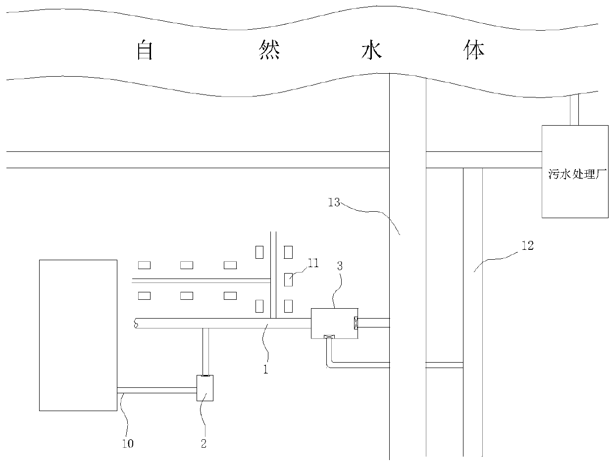
[0041] see figure 1 As shown, the existing combined pipe network system has a sewage branch pipe 10, a rainwater outlet 11 and a combined pipe 1 located in the unit area. The water flowing out of the unit area enters the municipal sewage pipe 12 and the municipal rainwater pipe 13. The sewage branch pipe in the unit area 10 and rainwater outlet 11 are respectively connected along the line of the confluence pipe 1, and the sewage branch pipe 10 and rainwater outlet 11 are connected in parallel along the line of the confluence pipe 1; the unit areas in the present embodiment are districts, hospitals, office buildings and other areas.

[0042] This embodiment provides a drainage system based on municipal road diversion pipe network, which is based on the transformation of the existing combined pipe network system. The system includes:

[0043] The intercepting part 2 is arranged near the access part where the sewage branch pipe 10 is connected to the confluence pipe 1 or upstream...

Embodiment 2

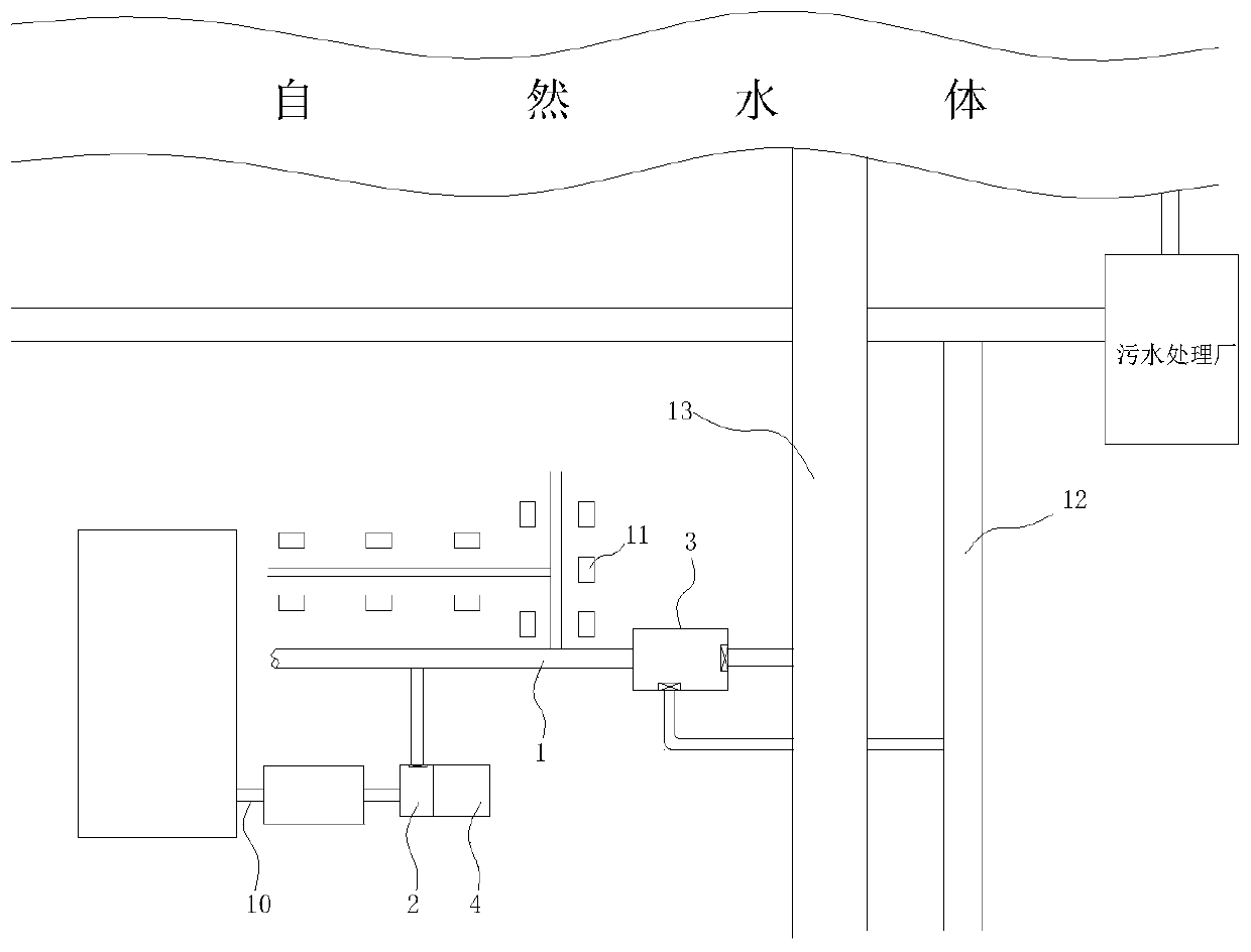
[0046] see figure 2 As shown, the existing combined pipe network system has a sewage branch pipe 10, a rainwater outlet 11, a sewage storage facility (such as a septic tank) and a combined pipe 1 located in the unit area, and a septic tank outlet and a rainwater outlet 11 in the unit area. They are respectively connected along the line of the confluence pipe 1, and the septic tank and the rainwater outlet 11 are connected in parallel along the line of the confluence pipe 1; the unit areas in this embodiment are districts, hospitals, office buildings and other areas.

[0047] The difference between this embodiment 2 and embodiment 1 is:

[0048] The intercepting part 2 in the embodiment 1 is arranged between the sewage branch pipe 10 and the confluence pipe 1 or the connecting part between the sewage branch pipe and the confluence pipe 1;

[0049] The intercepting part 2 in the embodiment 2 is arranged between the outlet of the septic tank and the confluence pipe 1 or at the ...

Embodiment 3

[0051] see figure 1 and figure 2 As shown, on the basis of Embodiment 1 and Embodiment 2, for the arrangement of sewage branch pipes, interceptors and sewage storage facilities:

[0052] Mode 1, the number of the sewage branch pipe is one, the number of the intercepting part 2 is one, and one sewage storage facility is arranged between one sewage branch pipe 10 and one intercepting part 2, The inlet of one intercepting part 2 is connected with the outlet of one sewage storage facility;

[0053] Mode 2, the number of the sewage branch pipes 10 is several, the number of the intercepting parts 2 and the number of the sewage storage facilities are all adapted to the number of the sewage branch pipes 10, and each of the sewage branch pipes 10 A corresponding sewage storage facility is arranged between the corresponding one of the intercepting parts 2, and the inlet of each of the intercepting parts 2 is connected to the outlet of the corresponding one of the sewage storage facil...


PUM


Abstract

The invention discloses a drainage system and a drainage method based on a municipal road separate pipe network. The drainage system comprises a confluence pipe, interception parts and a diversion facility. Sewage branch pipes and rainwater ports in unit areas are connected along the line of the confluence pipe separately; the interception parts are arranged close to the connection portions or atthe upstream positions of the connection portions, connected to the confluence pipe, of the sewage branch pipes, the interception parts are provided with inlets and first outlets, the inlets communicate with the sewage branch pipes, the first outlets communicate with the confluence pipe, and first water conservancy switches are arranged to control water passing through the first outlets; and the diversion facility is provided with an inlet, a third outlet and a fourth outlet, the inlet of the diversion facility is connected with the confluence pipe, the third outlet is connected with a municipal sewage pipe, the fourth outlet is connected with a municipal rainwater pipe, the diversion facility is located at the downstream position of the sewage branch pipes and the rainwater ports, the diversion facility is further provided with water conservancy switches for controlling water passing through the third outlet and the fourth outlet respectively, and the diversion facility is used for diverting dirty water to the municipal sewage pipe and diverting clean water to the municipal rainwater pipe.

Description

technical field [0001] The invention relates to the technical field of drainage, in particular to a drainage system and a drainage method based on municipal road diversion pipe network. Background technique [0002] The urban municipal road pipe network is divided into a combined pipe network system and a separate pipe network system. The existing drainage system for the municipal road diversion pipe network system is to mix sewage, industrial wastewater and rainwater in the same pipe. Discharge into natural water bodies will cause serious pollution to the receiving water body. If it is directly discharged into the sewage treatment plant for treatment, a large amount of relatively clean rainwater will enter the sewage treatment plant for unnecessary treatment in rainy days, resulting in waste of resources. [0003] It can be seen that in the prior art, for the diversion system pipe network, sewage and rainwater are mixed together, and when they are directly discharged into n...

Claims


Application Information

Patent Timeline
IPC IPC(8): E03F3/02E03F3/04G01D21/02
CPCE03F3/02E03F3/04E03F2201/10E03F2201/20G01D21/02
Inventor 李习洪周超
Owner WUHAN SHENGYU DRAINING SYST
Why Eureka
Try Eureka