Al technical title is built by PatSnap Al team. It summarizes the technical point description of the patent document.
A technology of automation equipment and cleaning device, applied in cleaning devices, transportation and packaging, conveyor objects, etc., can solve problems such as affecting the appearance or quality of conveyed objects, reducing the service life of conveyor belts, soiling conveyed objects, etc. The effect of strong, saving production time and prolonging service life
Pending Publication Date: 2020-08-28
GUANGDONG INST OF SCI & TECH
View PDF0 Cites 5 Cited by
Summary
Abstract
Description
Claims
Application Information
AI Technical Summary
This helps you quickly interpret patents by identifying the three key elements:
Problems solved by technology
Method used
Benefits of technology
Problems solved by technology
[0002] Conveyor is a kind of automatic equipment that is often used in daily processing and transportation, which can greatly improve the efficiency of transportation. With the wide use of conveyors, the cleaning of conveyor belts has attracted the attention of users, because the conveyor belt may not be clean. It will cause dirt or scratches on the conveyed objects, which will affect the appearance or quality of the conveyed objects, so the cleaning of the conveyor belt is particularly important
[0003] Nowadays, the cleaning of the conveyor belt is generally carried out by direct washing with a water gun or by removing it from the equipment. The uneven washing method will also cause a large amount of water stains to accumulate on the bottom of the equipment, which will affect the working environment; the disassembly cleaning method is accompanied by disassembly. It is difficult to assemble, time-consuming and labor-intensive, and affects the production time. Moreover, repeated disassembly can easily cause the conveyor belt to loosen and reduce the service life of the conveyor belt. Therefore, an automatic equipment cleaning device is urgently needed to solve the problem.
Method used
Image
Click on the blue label to locate the original text in one second.
Reading with bidirectional positioning of images and text.
Examples
Embodiment Construction
[0030] In order to enable those skilled in the art to better understand the present invention, the technical solution of the present invention will be further described below in conjunction with the accompanying drawings and embodiments.
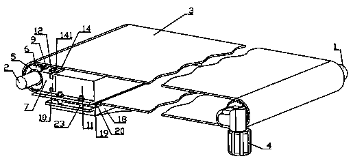
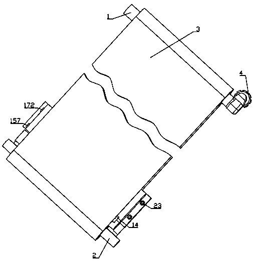
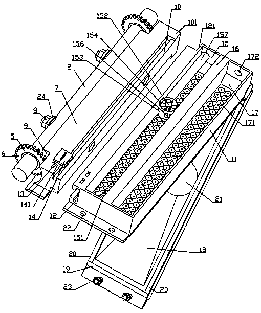
[0031] Such as Figure 1-Figure 6 As shown, a kind of automation equipment cleaning device of the present invention comprises driving roller 1, driven roller 2 and chain conveyer belt 3, and driving roller 1 power end is connected with motor 4, and bearing 5 is installed on driven roller 2, and driving roller 1 and the bearing 5 are equipped with a gear 6 matching the chain conveyor belt 3, the driven roller 2 is matched with a fixed block 7, the fixed block 7 and the driven roller 2 are provided with corresponding fixing through holes, and the fixed through holes are matched with a fixed Screw 8, fixed block 7 is provided with the give way arc groove 9 that matches with gear 6, and fixed block 7 is provided with T-shaped fixed block 10 inte...
PUM
Abstract
The invention discloses an automatic equipment cleaning device. The automatic equipment cleaning device comprises a driving roller, a driven roller and a chain conveyor belt, wherein the power end ofthe driving roller is connected with a motor, a bearing and a gear are installed on the driven roller, the driven roller is matched with a fixing block, the fixing block is provided with a fixing through hole and a fixing screw, the fixing block is provided with a receding arc-shaped groove and a T-shaped fixing block, the T-shaped fixing block is matched with a cleaning box, the cleaning box comprises a fixing groove and buckling grooves, the buckling grooves are matched with buckling blocks, the cleaning box comprises an air drying box, a separating block and a spraying box, the air drying box comprises an air outlet, a rotating shaft, an air box, fan blades, a cam, through holes and an air inlet pipe, the input end of the air inlet pipe is connected with a hot air blower, the separatingblock comprises a cross-shaped groove, a cross-shaped sliding block, a stopping table, a spring, an ejector rod and a U-shaped brush body, the spraying box comprises spraying holes and a water inlet,the input end of the water inlet is connected with a water supply device, and the cleaning box is hinged to a water receiving box, the water receiving box and the cleaning box are provided with limiting blocks and auxiliary brush bodies, and the output end of the water receiving box is provided with a drain hole, fixing holes and fastening screws.
Description
technical field [0001] The invention belongs to the field of cleaning devices, and in particular relates to a cleaning device for automatic equipment. Background technique [0002] Conveyor is a kind of automatic equipment that is often used in daily processing and transportation, which can greatly improve the efficiency of transportation. With the wide use of conveyors, the cleaning of conveyor belts has attracted the attention of users, because the conveyor belt may not be clean. It will cause soiling or scratching of the conveyed objects, which will affect the appearance or quality of the conveyed objects, so the cleaning of the conveyor belt is particularly important. [0003] Nowadays, the cleaning of the conveyor belt is generally carried out by direct washing with a water gun or by removing it from the equipment. The uneven washing method will also cause a large amount of water stains to accumulate on the bottom of the equipment, which will affect the working environm...
Claims
Application Information
Patent Timeline
Application Date:The date an application was filed.
Publication Date:The date a patent or application was officially published.
First Publication Date:The earliest publication date of a patent with the same application number.
Issue Date:Publication date of the patent grant document.
PCT Entry Date:The Entry date of PCT National Phase.
Estimated Expiry Date:The statutory expiry date of a patent right according to the Patent Law, and it is the longest term of protection that the patent right can achieve without the termination of the patent right due to other reasons(Term extension factor has been taken into account ).
Invalid Date:Actual expiry date is based on effective date or publication date of legal transaction data of invalid patent.