Motor rotor, motor and vehicle

A technology of motor rotor and rotor core, applied in the direction of electromechanical devices, electrical components, electric components, etc., can solve the problem that the motor rotor cannot be effectively dissipated, and achieve the effects of improving heat dissipation effect, assembly efficiency, and heat dissipation efficiency

Active Publication Date: 2020-10-13
HUAWEI DIGITAL POWER TECH CO LTD
View PDF3 Cites 19 Cited by
  • Summary
  • Abstract
  • Description
  • Claims
  • Application Information

AI Technical Summary

Problems solved by technology

[0005] The embodiment of the present application provides a motor rotor, motor and automobile, which solves the problem that the traditional motor ro

Method used


Image

  • Motor rotor, motor and vehicle
  • Motor rotor, motor and vehicle
  • Motor rotor, motor and vehicle

Examples


Embodiment Construction

[0095] The terms used in the embodiments of the present application are only used to explain specific embodiments of the present application, and are not intended to limit the present application.

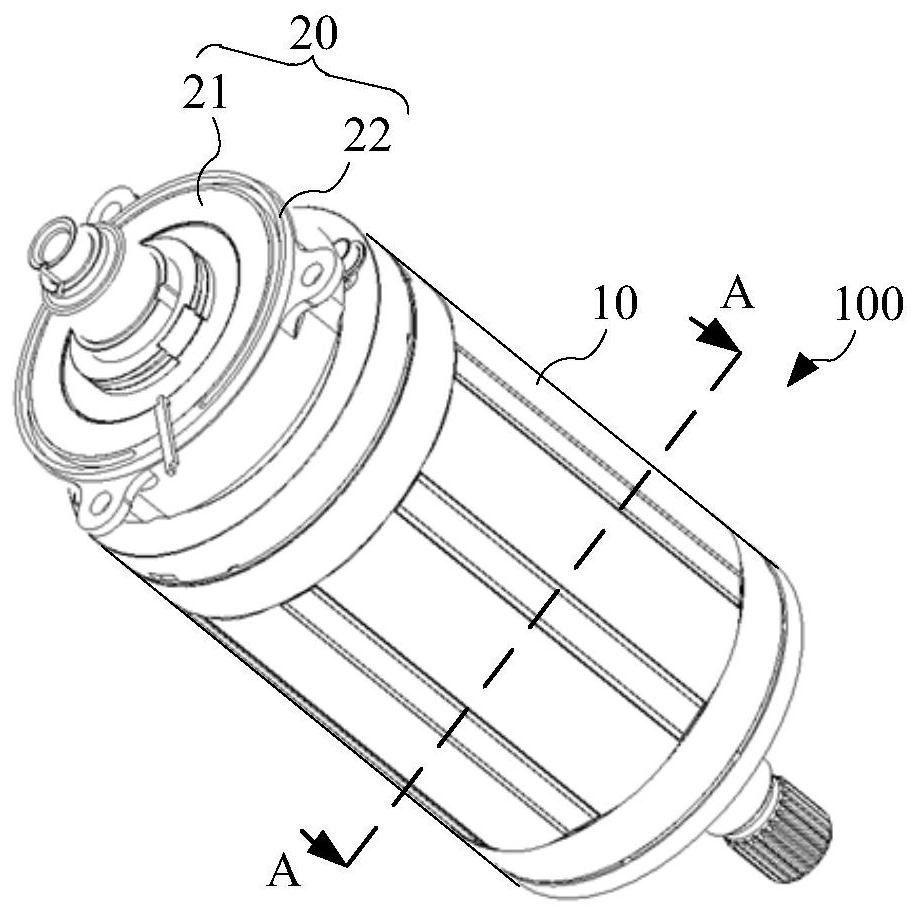
[0096] In the traditional technology, the motor includes a stator and a rotor, the stator is movably sleeved on the outer periphery of the rotor, and the rotor is connected to loads such as wheels. When working, the stator generates a rotating magnetic field in the air gap between the stator and the rotor. When the excitation winding of the rotor is fed with DC current, it will generate a static magnetic field with constant polarity. Under the action of the armature reaction, the rotor generates a magnetic field relative to the stator. Torque, thereby driving the load to move.

[0097] From the above working process of the motor, it can be known that the rotor of the motor needs to rotate at a high speed to drive the load to move, so compared with the stator, the heat generated dur...


PUM


Abstract

The embodiment of the invention provides a motor rotor, a motor and a vehicle, and the motor rotor comprises a winding rotor. The winding rotor comprises a rotating shaft, a rotor iron core and a plurality of rotor coils. The rotor iron core is fixedly sleeved on the rotating shaft, a plurality of winding holes are formed in the rotor iron core around the rotating shaft at intervals, each windinghole penetrates through the two ends of the rotor iron core arranged along the axial direction, each rotor coil is wound on the hole wall between two adjacent winding holes, and two adjacent rotor coils share one winding hole. A gap is formed between two adjacent rotor coils. A first shaft hole is formed in the rotating shaft. The gap is configured to be a first heat dissipation channel communicated with the first shaft hole, and the first heat dissipation channel is used for cooling liquid flowing into the rotating shaft, so that the cooling liquid introduced into the rotating shaft from theoutside can enter the first heat dissipation channel from the first shaft hole under the action of centrifugal force to dissipate heat of the rotor coil of the wound rotor, and the heat dissipation efficiency of the rotor coil is effectively improved.

Description

technical field [0001] The embodiments of the present application relate to the technical field of drive equipment, and in particular to a motor rotor, a motor and an automobile. Background technique [0002] Because the excitation motor does not need to use magnetic steel, and the excitation of the excitation motor rotor can be adjusted, it has the characteristics of low cost, no risk of demagnetization, and high driving efficiency. The motor can be used as driving equipment in the fields of automobile main drive and auxiliary drive system, factory granulation system, etc. [0003] In the related art, an excitation motor includes a stator and a rotor, the stator is movably sleeved on the outer periphery of the rotor, and the rotor is used for connecting with a load. When working, the rotor rotates relative to the stator under the action of the rotating magnetic field generated by the stator, thereby driving the load to move. In order to ensure that the rotor of the excita...

Claims


Application Information

Patent Timeline
IPC IPC(8): H02K1/32H02K9/197H02K1/26H02K3/487H02K3/12
CPCH02K1/32H02K9/197H02K1/265H02K3/487H02K3/12H02K2213/03H02K1/24H02K3/24H02K1/325H02K9/19H02K11/0094H02K19/12H02K1/12H02K1/26H02K9/14
Inventor 陈金华毋超强周朝黄建新王少华
Owner HUAWEI DIGITAL POWER TECH CO LTD
Why Eureka
Try Eureka