Protection device for orthopedic spine

A protection device and spine technology, applied in the field of orthopedic spine protection devices, can solve problems such as poor correction and protection of the spine, limited correction of the cervical spine, and failure to achieve protection effects, etc., to improve rehabilitation effects, reduce spinal injuries, Improve the effect of massage effect

Active Publication Date: 2020-10-16
泉州烜之璟医疗设备有限公司
View PDF10 Cites 2 Cited by
  • Summary
  • Abstract
  • Description
  • Claims
  • Application Information

AI Technical Summary

Problems solved by technology

[0003] If the spine is damaged, it will have a great impact on the normal movement of the human body. Therefore, when the spine is damaged, it is necessary to protect it in time and assist in its recovery, so as to ensure the normal movement of the human body. Most of the existing spinal protection devices are It is to tie the corresponding vertical plate on the back of the human body, correct the sitting posture to keep the spine in a normal state, and then restore it through massage. However, for most people today, the most serious part of the spinal column is the cervical spine. Due to the long It is caused by looking down and playing with mobile phones for a long time, but the existing devices have limited correction for the cervical spine. Although they can correct the middle and lower parts of the spine, they are not effective in correcting and protecting the top of the spine. For people who love to play with mobile phones and other electronic products A good protective effect cannot be achieved. In addition, the existing massage achieves a massage effect through the vibration of the massage ball, but the massage effect is limited

Method used


Image

  • Protection device for orthopedic spine
  • Protection device for orthopedic spine
  • Protection device for orthopedic spine

Examples


Embodiment 1

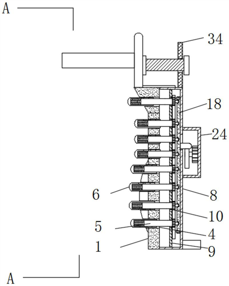
[0041] see Figure 1-13 , according to an embodiment of the present invention, an orthopedic spine protection device includes a vertical plate 1, the top of the vertical plate 1 is fixedly connected with a top plate 2, and the bottom of one side of the vertical plate 1 is fixedly connected with an arc convex plate 3 , the surface of the vertical plate 1, the top plate 2 and the curved convex plate 3 are all provided with a through hole 4, the inside of the through hole 4 is provided with a rotating sleeve 5, and one end of the rotating sleeve 5 is covered with a massage cover 6, so The port of the massage cover 6 is located outside the through hole 4, and it should be noted that the port of the massage cover 6 located outside the through hole 4 is a spherical surface;

[0042] A limiting mechanism is connected between the massage cover 6 and the rotary cover 5, a spring 7 is connected between the inside of the massage cover 6 and the port of the rotary cover 5, the vertical pl...

Embodiment 2

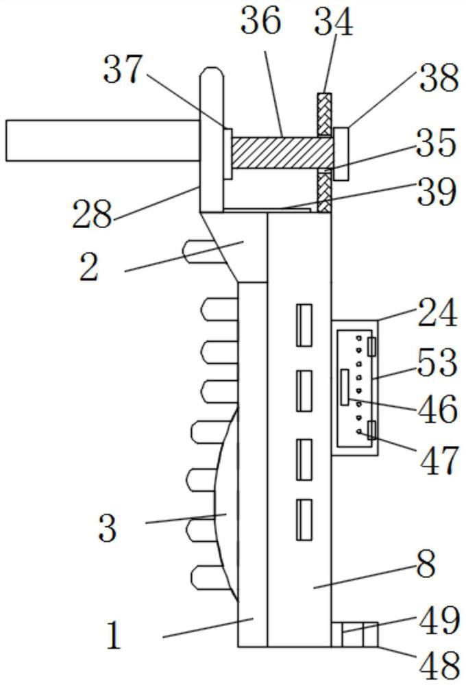
[0048] see Figure 1-2 with Figure 10 , the adjustment mechanism includes a support plate 34, a screw hole 35, a screw rod 36, a bearing 2 37 and a rotating block 38, the top of the fixed box 8 is fixedly connected with a support plate 34, and the inside of the support plate 34 has a screw hole 35, the internal thread of the screw hole 35 is connected with a screw 36, one end of the screw 36 is connected to the bonding plate 28 through a bearing 2 37, the other end of the screw 36 is fixedly connected to the rotating block 38, and the adjusting mechanism The position of the fitting plate 28 can be adjusted, so that the fitting plate 28 can be in close contact with the wearer's head, thereby achieving the purpose of limiting. The top of the top plate 2 and the vertical plate 1 are fixedly connected with a limit rod 39, and the fitting plate 28 and close to the limit bar 39 to open a limit groove 40, the limit bar 39 is located in the limit groove 40 and matches with the limit...

Embodiment 3

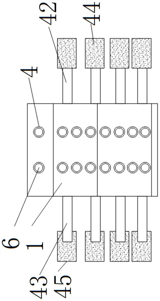
[0050] see image 3 , the binding mechanism includes three binding straps 42, four binding straps 43, two Velcro stickers 44 and two Velcro female stickers 45, one side of the fixed box 8 is fixedly connected with three binding straps 42, and the three binding straps 42 Two Velcro stickers 45 are fixedly connected to the port of the fixed box 8, and one side of the fixed box 8 away from the three straps 42 is fixedly connected with four straps 43, and the port of the four straps 43 is fixedly connected with two Velcro stickers. 44. The second Velcro sticker 45 is matched with the second Velcro sticker 44, and the binding mechanism can fix the device on the wearer's spine, so as to achieve the purpose of fixing, so that the device fits the wearer's spine.


PUM


Abstract

The invention discloses a protection device for orthopedic spine. The device comprises a vertical plate, the top of the vertical plate is fixedly connected with a top plate, the bottom of one side ofthe vertical plate is fixedly connected with an arc convex plate, the vertical plate, the top plate and the surface of the arc convex plate is provided with through holes, a rotating sleeve is arranged inside the through hole, one end of the rotating sleeve is covered with a massage sleeve, a spring one is connected between the inside of the massage sleeve and the port of the rotating sleeve, oneside of the vertical plate and the top plate far away from the massage sleeve is fixedly connected with a fixed box, the inside of the fixed box is fixedly connected with a fixed plate, the rotating sleeve is movably connected with the fixed plate through a bearing one, the outer surface of the rotating sleeve is fixedly connected with gears, the gears are meshed with tooth plates, both sides of the fixed box are provided with binding mechanisms, the top of the top plate is provided with a laminating plate, and the laminating plate is connected with an adjustment mechanism. The beneficial effects are that the spine can be protected and massaged, and the pain caused by spinal injury can be relieved.

Description

technical field [0001] The invention relates to the technical field of orthopedic spine, in particular to a protective device for orthopedic spine. Background technique [0002] The upper end of the spine supports the skull, connects the hip bones below, attaches the ribs in the middle, and serves as the back wall of the thorax, abdomen, and pelvis. The spine has the functions of supporting the trunk, protecting the internal organs, protecting the spinal cord and performing movements. Various activities of the upper and lower limbs are regulated by the spine to maintain body balance. The four physiological curvatures of the spine make the spine act like a spring, which can increase the ability to buffer shocks and strengthen the stability of the posture. The intervertebral disc can also absorb shocks. During strenuous exercise or jumping, it can prevent the skull and brain from being damaged. The thorax, sternum, and hip make up the thorax and pelvis, which play an importa...

Claims


Application Information

Patent Timeline
Patent Type & Authority Applications(China)
IPC IPC(8): A61H7/00A61H23/02A61F5/01
CPCA61H7/00A61H23/02A61F5/01A61H2201/1207A61H2201/1671A61H2205/08A61H2201/0149
Inventor 张鹭
Owner 泉州烜之璟医疗设备有限公司
Why Eureka
Try Eureka