A Low Profile Ground Penetrating Radar Antenna

A ground-penetrating radar, low-profile technology, applied in the field of electromagnetic fields and microwaves, can solve the problems of reduced efficiency, reduced antenna bandwidth, and deterioration of time-domain performance, to achieve the effect of expanding bandwidth, reducing low-frequency cut-off frequency, and good time-domain characteristics

Active Publication Date: 2021-12-28
XI AN JIAOTONG UNIV
View PDF14 Cites 0 Cited by
  • Summary
  • Abstract
  • Description
  • Claims
  • Application Information

AI Technical Summary

Problems solved by technology

However, the miniaturization of the antenna means the reduction of bandwidth and the reduction of efficiency, which leads to the deterioration of time domain performance
At present, there is a lack of miniaturized GPR antenna design with excellent time-domain performance in this field

Method used


Image

  • A Low Profile Ground Penetrating Radar Antenna
  • A Low Profile Ground Penetrating Radar Antenna
  • A Low Profile Ground Penetrating Radar Antenna

Examples


Embodiment

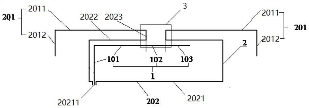
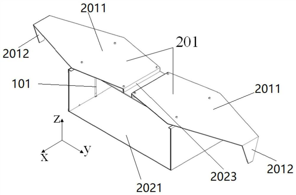
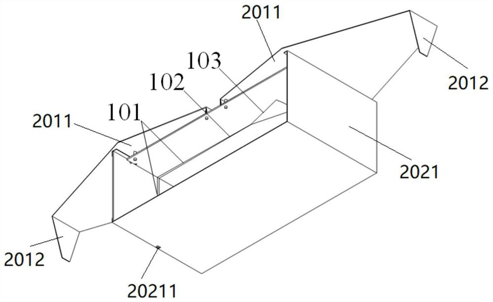
[0044] In order to ensure the stability of the overall structure, the probe and the radiation part close to the probe are made of double-sided printed F4BM-2 (dielectric constant 2.2) dielectric board to ensure that the distance between the probe and the metal plate is 3mm, and the rest Some parts are made of aluminum plate, and the antenna structure is as follows: figure 1 as well as Figure 2(a) ~ Figure 2(d) As shown, the parameter values ​​are listed in Table 1.

[0045] Table 1

[0046]

[0047] Wherein, W1 is the overall width of the antenna, W2 is the width of the constant width part 102, W3 is the width of the tapered microstrip line part 101 located at the feeding port 20211, W4 is the length of one side of the second horizontal metal plate 2011, the The side is a side parallel to the side of the inner end of the second horizontal metal plate 2011, L1 is the overall length of the antenna, L2 is the distance between the two wings of the U-shaped metal plate, and L...


PUM


Abstract

The invention discloses a low-profile ground-penetrating radar antenna, which includes a feeding probe and a radiator. The radiator includes an electric dipole and a magnetic dipole. Both wing ends of a U-shaped metal plate are vertically connected with a first Horizontal metal plates, the end of the first horizontal metal plate extends to the symmetrical axis of the U-shaped metal plate, the end of the vertical metal plate is vertically connected with the second horizontal metal plate, and the two second horizontal metal plates form an electric dipole ; The shape of the second horizontal metal plate is an axisymmetric hexagon or octagon, which is connected with the vertical metal plate; the feeding probe is arranged inside the U-shaped metal plate, and the width constant part and the fan-shaped stub are arranged horizontally , the part with constant width is located directly below the two vertical metal plates, the length of the constant width part is equal to the distance between the two vertical metal plates, and the part of the gradient microstrip line extends horizontally to one wing of the U-shaped metal plate The edge is bent vertically downward at a preset distance, and its vertical part extends to the feed port. The antenna of the invention has wide bandwidth and good time domain characteristics.

Description

technical field [0001] The invention belongs to the technical field of electromagnetic fields and microwaves, and relates to a ground penetrating radar antenna. Background technique [0002] Ground-penetrating radar systems have important applications in geological detection, mineral exploration, and life detection. In addition to meeting the system bandwidth and pattern requirements, the GPR antenna needs to radiate and receive pulse signals without distortion. Chromatic dispersion is an important factor causing antenna radiation pulse distortion, so the design goals of pulsed antennas are ultra-wideband, low dispersion, high efficiency and high directivity. [0003] The ground penetrating radar system generally determines the working center frequency according to the requirements of the detection distance. Considering the loss, the system frequency is generally lower than 5GHz. Antennas working at low frequencies usually have relatively large dimensions. In order to impr...

Claims


Application Information

Patent Timeline
Patent Type & Authority Patents(China)
IPC IPC(8): H01Q9/28H01Q1/36H01Q1/38H01Q1/50
CPCH01Q9/28H01Q1/36H01Q1/38H01Q1/50
Inventor 张安学崔嘉倩师振盛李建星舒敏杰
Owner XI AN JIAOTONG UNIV
Why Eureka
Try Eureka