Injection mold

A technology for injection molds and moving molds, which is applied in the field of injection molds, and can solve problems such as stain marks and injection lines on injection molded parts, quality reduction of injection molded parts, and ejection of molded parts.

Active Publication Date: 2020-10-23
苏州宇鑫精密模具有限公司
View PDF2 Cites 1 Cited by
  • Summary
  • Abstract
  • Description
  • Claims
  • Application Information

AI Technical Summary

Problems solved by technology

[0005] 1. Since the injection molded part itself still has a certain temperature when it is withdrawn from the mold, there is too much stress inside, the molding strength is not enough, and it has a certain degree of plasticity. The moment the hydraulic device 1 is driven, the inner walls of the movable mold 3 and the fixed mold 4 Create a resistance along the outer wall of the injection molded part on the outer wall of the injection molded part, which will cause the surface deformation of the injection molded part and reduce the molding quality of the injection molded part;
[0006] Secondly, when the mold is withdrawn, the ejector rod 2 will eject the injection molded part. When ejecting, the internal stress of the injection molded part will also be large, which will cause the injection molded part to bend when it is ejected, which will further affect the molding quality of the injection molded part.
[0007] 2. Due to the different resistance between the injection molded part and the fixed mold 4 and the movable mold 3, it often happens that the molded part cannot be withdrawn from the mold together with the movable mold 3, which makes it difficult to take out the molded part and affects the injection molding efficiency
[0008] 3. During the mold ejection process, since the initial state of the injection molded part is molten, after its molding, some residual injection molded particles will remain on the inner wall of the cavity 6 (the inner wall of the movable mold 3 and the fixed mold 4), especially There will be cold material at the gate area. If it is not cleaned up in time, stains and injection marks will appear on the surface of the injection molded part when it is injected again, resulting in a decrease in the quality of the injection molded part.

Method used


Image

  • Injection mold
  • Injection mold
  • Injection mold

Examples


Embodiment 1

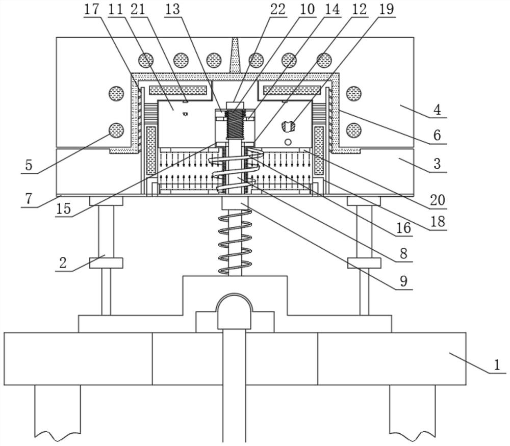
[0041] see Figure 1-11, an injection mold, comprising a hydraulic device 1, a hydraulic rod 2, a movable mold 3 and a fixed mold 4, the hydraulic device 1 and the movable mold 3 are connected through a hydraulic rod 2, and a mold is formed between the movable mold 3 and the fixed mold 4 Cavity 6, this mold cavity 6 can be set according to the different injection molded parts, 3 is provided with a cooling water channel 5, the middle part of the fixed mold 4 is provided with a pouring port, the pouring port is connected with the cavity 6 and the pouring port is connected with the injection molding machine, and the movable mold The middle part of 3 is groove-shaped and the groove is connected to the mold cavity 6. A wall shape with a certain thickness is formed around the movable mold 3. Four sets of negative pressure air passages 17 are opened around the movable mold 3. Four sets of negative pressure air passages 17 connects the mold cavity 6 with the groove of the movable mold...

Embodiment 2

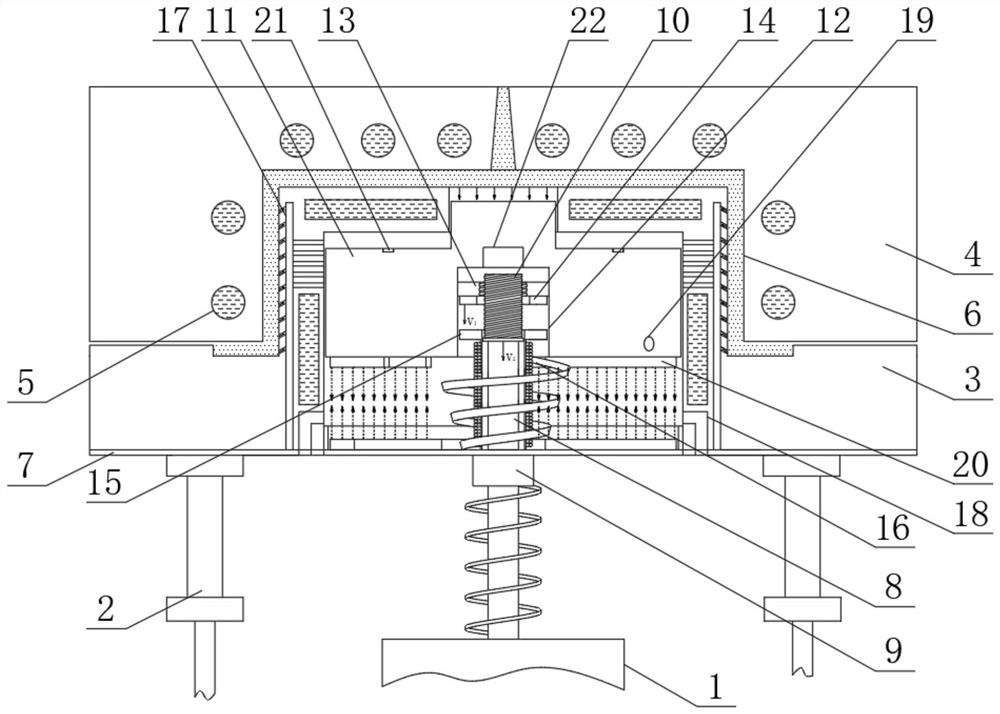
[0052] Reference attached Figure 12 , different from Embodiment 1, the section of the driving rod 8 located inside the hollow electromagnet 15 can be hollow, and the middle part of the driving rod 8 can fix the iron core, so as to enhance the electromagnetic force of the hollow electromagnet 15, thereby ensuring Under the action of electromagnetic force, the sealing member 11 can move down, and the moving speed is faster than the moving speed of the movable mold 3, so as to ensure that the negative pressure is also generated at the same time when the mold can be demoulded, and the magnitude of the negative pressure is gradually changing sexual increase.

[0053] The principle of injection molding is as follows

[0054] Cooling forming stage:

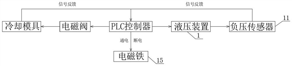
[0055] After the injection molding machine injects the melted raw material of the injection molded part into the cavity 6 through the injection port, the PLC controller controls the solenoid valve to open, and starts to inject cold wa...


PUM


Abstract

The invention relates to the technical field of injection molds, and discloses an injection mold. The injection mold comprises a hydraulic device, a hydraulic rod movable mold and a fixed mold, wherein the hydraulic device is in transmission connection with the movable mold through a hydraulic rod, a mold cavity is formed between the movable mold and the fixed mold, a cooling water channel is formed in the mold cavity, a pouring opening is formed in the middle of the fixed mold, the pouring opening communicates with the mold cavity and communicates with an injection molding machine, the middleof the movable mold is in a groove shape, the groove communicates with the mold cavity, a sealing piece is driven to move downwards under the action of a hollow electromagnet, and therefore gradually-changed negative pressure is formed between the sealing piece and the movable mold firstly. The gradually-changed negative pressure acts on the injection molding piece, slow separation between the outer wall of the injection molding piece and the inner wall of the fixed mold can be guaranteed, bonding resistance between the injection molding piece and the fixed mold disappears, separation from the fixed mold is achieved while the movable mold moves downwards, in the demolding process, the surface of the injection molding piece is not bonded with the fixed mold during demolding, resistance isrelatively small, and the surface quality of the injection molding piece during demolding is improved.

Description

technical field [0001] The invention relates to the technical field of injection molds, in particular to an injection mold. Background technique [0002] Injection molding, also known as injection molding, is a molding method of injection and molding. It stirs the completely molten plastic material through a screw at a certain temperature, injects it into the mold with high pressure, and obtains a molded product after cooling and solidification. For mass production of parts with complex shapes. [0003] See attached Figure 13 , when the existing mold is being molded, the molten plastic material is injected into the mold cavity between the fixed mold 4 and the movable mold 3 through the injection port, and is cooled and formed through the cooling channel 5 of the fixed mold 4 and the movable mold 3, after molding , the hydraulic device 1 drives the movable mold 3 to separate from the fixed mold 4, and after the movable mold 3 is separated from the fixed mold 4, the molded i...

Claims


Application Information

Patent Timeline
Patent Type & Authority Applications(China)
IPC IPC(8): B29C45/34B29C45/26B29C45/43
CPCB29C45/34B29C45/2608B29C45/43
Inventor 吴华
Owner 苏州宇鑫精密模具有限公司
Why Eureka
Try Eureka