Control method, device, system and electric vehicle of wireless charging system

A technology of wireless charging and control methods, applied in electric vehicles, circuit devices, battery circuit devices, etc., can solve the problems of high integration and unfavorable modular design of wireless charging systems, and achieve the effect of reducing design difficulty and increasing safety.

Active Publication Date: 2021-02-09
深圳赫兹创新技术有限公司
View PDF4 Cites 0 Cited by
  • Summary
  • Abstract
  • Description
  • Claims
  • Application Information

AI Technical Summary

Problems solved by technology

[0005] An embodiment of the present invention provides a control method for a wireless charging system, aiming to solve the problem that the existing wireless charging system is highly integrated and not conducive to modular design

Method used


Image

  • Control method, device, system and electric vehicle of wireless charging system
  • Control method, device, system and electric vehicle of wireless charging system
  • Control method, device, system and electric vehicle of wireless charging system

Examples


Embodiment 1

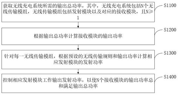
[0077] In some alternative examples, please refer to image 3 , image 3 It is a schematic flowchart of an embodiment of a control method of a wireless charging system in the present application.

[0078] Such as image 3 As shown, the first aspect of the present application provides a control method for a wireless charging system, including:

[0079] S1100. Obtain the total output power required by the wireless charging system, wherein the wireless charging system includes N wireless transmission modules, the wireless transmission module includes a transmitting module and a corresponding receiving module, and N≥1;

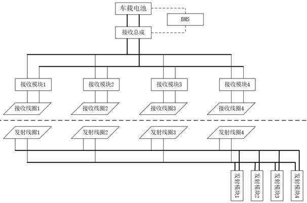
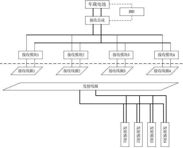
[0080] During implementation, the wireless charging system includes a receiving end and a transmitting end, wherein the receiving end includes N receiving modules, and the transmitting end includes N transmitting modules. A transmitting module and a receiving module are set in pairs to form a wireless transmission module. The receiving module The output power i...

Embodiment 2

[0100] In some alternative embodiments, see Figure 5 , Figure 5 It is a schematic flow chart of calculating the output power of the receiving module in an embodiment of the present application.

[0101] Such as Figure 5 As shown, the steps of calculating the output power of the receiving module according to the total output power include:

[0102] S1210. Obtain the rated output power of the receiving module;

[0103] S1220. According to the total output power and the rated output power, calculate and confirm the quantity information of the receiving modules participating in the wireless power transmission and the output power of each receiving module.

[0104] During implementation, the rated output power is the maximum output power of the receiving module under normal working conditions. The system calculates the number of receiving modules participating in wireless power transmission according to the total output power and the rated output power, as well as the output ...

Embodiment 3

[0106] In some alternative embodiments, see Image 6 , Image 6 It is a basic flow chart of an embodiment of the present application to control part of the transmission module to stop working.

[0107] Such as Image 6 As shown, after the step of controlling the output transmission power of the corresponding transmitting modules so that the sum of the output powers of the N receiving modules meets the total output power, the control method of the wireless charging system provided by the present application further includes the following steps:

[0108] S1510. Obtain a charging current signal required by the target battery, wherein the charging power of the target battery is the total output power;

[0109] During the implementation, during the charging process of the target battery, as the power is gradually full, the charging power will decrease, that is, the charging current required by the target battery will also decrease. The system monitors the charging current signal ...


PUM


Abstract

The present invention is applicable to the technical field of wireless charging, and provides a control method, device, system and electric vehicle of a wireless charging system. The method includes: obtaining the total output power required by the wireless charging system, wherein the wireless charging system includes N wireless The transmission module, the wireless transmission module includes the transmission module and the corresponding receiving module, and N≥1; calculate the output power of the receiving module according to the total output power; for each wireless transmission module, according to the preset wireless transmission rules and output The power calculates the transmit power of the corresponding transmit module; controls the output transmit power of the corresponding transmit module so that the sum of the output powers of the N receiving modules meets the total output power. The transmitting module and receiving module of the embodiment of this application adopt a modular design, and each transmitting module and receiving module can work independently to meet the total output power of the wireless charging system, and can increase or decrease the capacity of the module according to the actual situation. Reduced design difficulty.

Description

technical field [0001] The invention belongs to the technical field of wireless charging, and in particular relates to a control method, device, system and electric vehicle of a wireless charging system. Background technique [0002] As an ideal power supply method, wireless power transfer (WPT) has been rapidly developed and widely used in equipment power supply, such as electric vehicle charging, due to its advantages of high safety, large charging range and good controllability. [0003] For high-power automotive wireless charging systems, it is usually necessary to connect multiple receiving modules in parallel to achieve greater power output. For example, if the output power is 60kW and a single receiving module outputs 15kW, four receiving modules need to be connected in parallel. Correspondingly, the transmitting end usually adopts the form of a large coil or multiple transmitting coils. Since the output power of the system is relatively large, such as 60kW, the power...

Claims


Application Information

Patent Timeline
Patent Type & Authority Patents(China)
IPC IPC(8): H02J50/40H02J50/80H02J50/10H02J7/00B60L53/12B60L53/60B60L53/62B60L53/66
CPCB60L53/12B60L53/60B60L53/62B60L53/66H02J50/10H02J50/40H02J50/80H02J7/00712H02J7/00714Y02T10/70Y02T10/7072Y02T90/12Y02T90/14Y02T90/16
Inventor 胡锦敏梁立科侯延进何智
Owner 深圳赫兹创新技术有限公司
Why Eureka
Try Eureka