Engine box body positioning structure

A positioning structure and engine technology, applied in the direction of the injection device, etc., can solve the problems of damage to the casing, paint sprayed into the chamber of the box, easy to move, etc., and achieve the effect of improving stability

Active Publication Date: 2020-12-08
江西博展自动化科技有限公司
View PDF4 Cites 0 Cited by
  • Summary
  • Abstract
  • Description
  • Claims
  • Application Information

AI Technical Summary

Problems solved by technology

[0004] The existing spraying operation method is to place the shell box on the pallet (the through hole of the box body is located at the top position), and then place the cover plate adapted to the top of the shell box on the shell box to cover the box connection. The through hole, the shutter also has an extension section that can cover the through hole of the box body, and then it is sprayed, but this method has the following problems: 1. Since no positioning structure is provided, the shell box body only It is placed on the pallet by its own weight, and the spraying has a certain impact force. During the spraying process, it is very easy to move the housing box. In the lightest case, the paint will be sprayed into the housing cavity of the box body to cause pollution, and in the worst case, the housing box will be damaged. body detached from the pallet and damage the enclosure
2. The shroud is placed directly on the housing box without a locking structure. During the spraying process, the shroud is also easily moved due to the impact force, causing the problem that the paint is sprayed into the housing cavity
3. After the spraying treatment, the paint on the shell box will be dried, and the adhesion problem will occur at the connection between the shell box and the pallet due to the drying of the paint, which is not conducive to the cutting work of the shell box

Method used


Image

  • Engine box body positioning structure
  • Engine box body positioning structure
  • Engine box body positioning structure

Examples


Embodiment 1

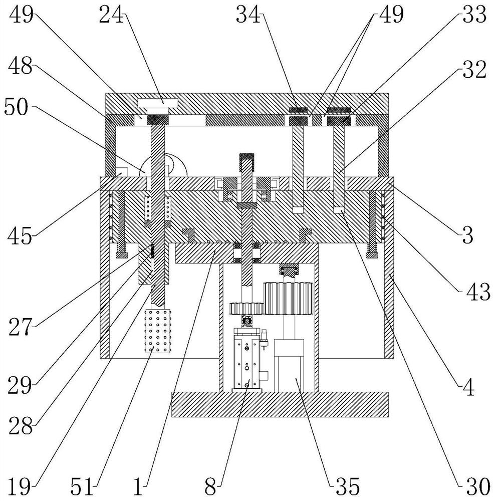
[0061] Such as Figure 1 to Figure 11 As shown, the positioning structure of the engine case includes a support base 1 and a shielding plate 21, and a positioning seat 2 is connected to the support base 1;

[0062] The positioning seat 2 is movable up and down and is connected with a locking rod 19 which can rotate circumferentially. The top of the locking rod 19 runs through the top of the positioning seat 2, and the top of the locking rod 19 is also connected with a Circular locking block 20;

[0063] The positioning seat 2 is also provided with a locking rod elastic part 22, and the locking rod elastic part 22 acts on the locking rod 19, so that the locking rod 19 is located at the extreme position of downward movement, and the locking block 20 is located at the movable plate 3 above;

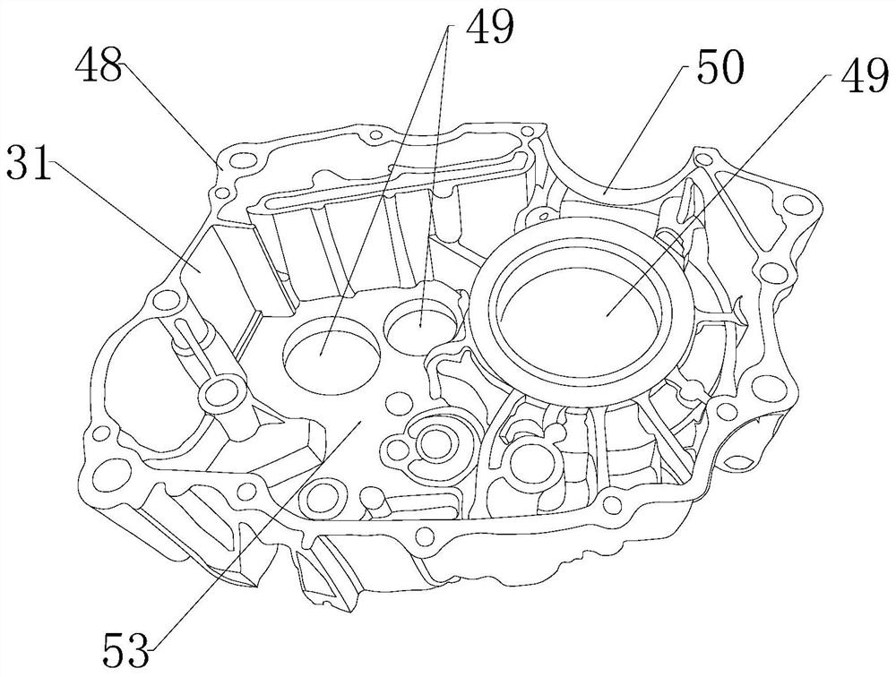
[0064] The side end of the shielding plate 21 also has a shielding extension 23, and the bottom end of the shielding plate 21 is provided with a locking groove 24 that can cooperate with t...

Embodiment 2

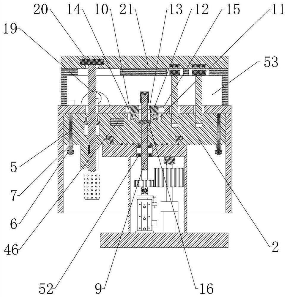
[0070] This embodiment makes the following further limitations on the basis of Embodiment 1: the positioning seat 2 is provided with a positioning seat annular groove 25, and the locking rod 19 is sleeved and connected with a ring that can rotate in the positioning seat annular groove 25 And the locking rod moving up and down abuts against the ring 26;

[0071] The locking rod elastic member 22 is sheathed on the locking rod 19 , and the upper and lower ends of the locking rod elastic member 22 abut against the top of the annular groove 25 of the positioning seat and the top of the locking rod abutting ring 26 respectively.

[0072] In this embodiment, through the cooperation between the locking rod abutment ring 26 and the annular groove 25 of the positioning seat, not only can the relative rotation between the locking rod 19 and the positioning seat 2 be realized, but also be used to limit the locking rod 19 up and down. The extreme position of movement avoids excessive move...

Embodiment 3

[0074] This embodiment makes the following further limitations on the basis of Embodiment 1: the locking rod 19 is provided with a circumferential locking groove 27 and a circumferential limiter located below the circumferential locking groove 27 and communicating with the circumferential locking groove 27. Position groove 28, the opening arc length of the circumferential limiting groove 28 along the circumferential direction of the locking rod 19 is greater than the opening arc length of the circumferential locking groove 27 along the circumferential direction of the locking rod 19;

[0075] The positioning seat 2 is also provided with a circumferential locking protrusion 29 which can fit into the circumferential locking groove 27 , and the circumferential locking protrusion 29 can be located in the circumferential limiting groove 28 .

[0076] In this embodiment, the bottom end of the circumferential locking groove 27 communicates with the top end of one end of the circumfere...


PUM


Abstract

The invention discloses an engine box body positioning structure which comprises a supporting base and a shielding plate. A positioning base is connected to the supporting base. A locking rod is connected to the positioning base. A locking rod elastic part is also arranged on the positioning base. A shielding extension section is further arranged at the side end of the shielding plate. A locking groove capable of being matched with a locking block is formed in the bottom end of the shielding plate. The locking groove is formed in the manner that an opening is small and an inner cavity is large. The locking block can penetrate through the opening of the locking groove to be located in the inner cavity of the locking groove. The locking block can rotate in the inner cavity of the locking groove. According to the structure, by arranging the locking rod and the shielding plate, the shielding plate can be locked to the top end of a shell box body only by moving and rotating the locking rod,in this way, the shell box body can be positioned, the shielding plate can also be positioned, and the situation that the shell box body and the shielding plate move accidentally is avoided. By meansof cooperation between a magnetic part and a metal part, positioning stability can be further improved.

Description

technical field [0001] The invention belongs to the technical field of engines, and in particular relates to an engine casing positioning structure. Background technique [0002] The engine is a device that provides power. In order to ensure the stability of the engine operation, the engine is usually placed in the engine casing, which has the effects of shock resistance, heat dissipation, and noise reduction. Taking a motorcycle engine as an example, the engine housing includes a housing case and a housing case cover connected to the outside of the housing case. During the production and processing of the engine casing, the surface needs to be sprayed (spraying primer, topcoat, etc.). Since the casing box is located in the middle position, when spraying, only the peripheral surface of the casing box needs to be treated. That's it. [0003] Such as figure 1 Shown is a schematic structural diagram of the housing box, which has a housing chamber, a housing connection throug...

Claims


Application Information

Patent Timeline
Patent Type & Authority Applications(China)
IPC IPC(8): B05B13/02B05B12/20
CPCB05B13/0221B05B12/20
Inventor 张雪松
Owner 江西博展自动化科技有限公司
Why Eureka
Try Eureka