Auxiliary device for adjusting the force of jacking pipe

An auxiliary device and adjustable technology, which is applied in pipeline laying and maintenance, pipes/pipe joints/fittings, mechanical equipment, etc., can solve problems such as cracks in pipe jacking, and achieve cost reduction, quantity reduction, and rational construction methods Effect

Active Publication Date: 2022-05-13
CHINA MCC17 GRP
View PDF20 Cites 0 Cited by
  • Summary
  • Abstract
  • Description
  • Claims
  • Application Information

AI Technical Summary

Problems solved by technology

[0006] The technical problem to be solved by the present invention is to solve the post-maintenance problems such as cracks caused by different jacking force distributions of pipe jacking

Method used


Image

  • Auxiliary device for adjusting the force of jacking pipe
  • Auxiliary device for adjusting the force of jacking pipe
  • Auxiliary device for adjusting the force of jacking pipe

Examples


Embodiment 1

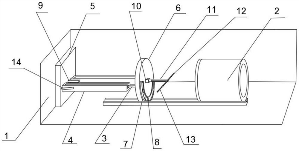
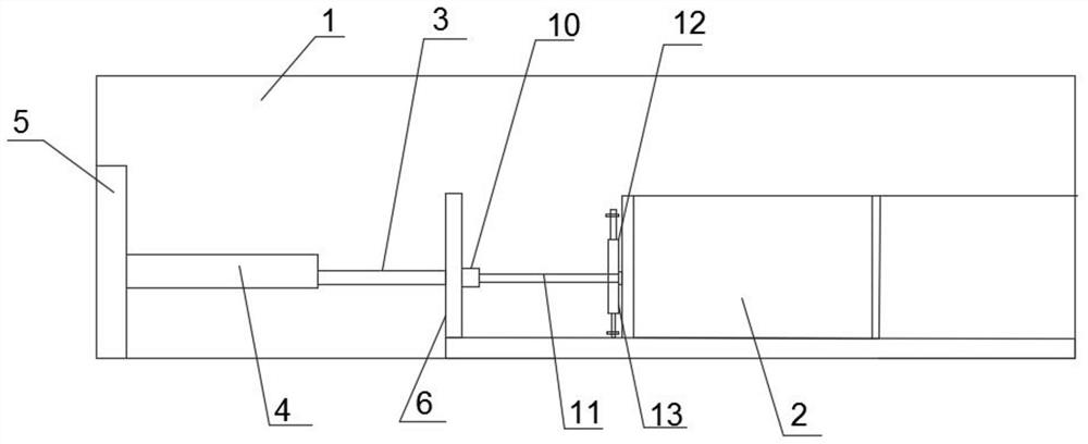
[0042] Such as Figure 1 to Figure 5 Shown: an auxiliary device that can adjust the force of pipe jacking, including pipe jacking pit 1, pipe jacking 2 and jack 3, and also includes limit rod 4, first connecting plate 5, second connecting plate 6 and fitting parts , there is a groove in the limit rod 4, the shell body of the jack 3 is installed in the groove, one side of the first connecting plate 5 is connected with the wall bolt of the pipe jacking pit 1, and the other side of the first connecting plate 5 is connected with Limit rod 4 welding;

[0043] The second connecting plate 6 is positioned at the end of the stop bar 4 away from the first connecting plate 5, the second connecting plate 6 is welded with the plunger of the jack 3, and the side of the jack 3 facing away from the plunger is welded with the first connecting plate 5 ;

[0044] The bonding parts include an arc-shaped crawler frame 7 and a push cylinder 8, the arc-shaped crawler frame 7 is located on the side o...

Embodiment 2

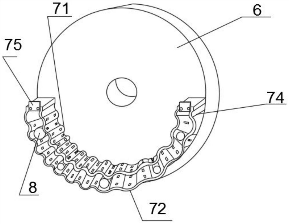
[0061] Such as Image 6 As shown, the installation method of the arc-shaped upper piece 71 and the arc-shaped lower piece 72 is changed to the groove and convex groove at the joint, and a stopper is provided at the end of the groove away from the second connecting plate 6, and the arc-shaped upper piece One side of the connection of 71 is a groove, and the other side of the connection of the arc-shaped upper sheet 71 is a convex groove. Similarly, the two sides of the connection of the arc-shaped lower sheet 72 are respectively provided with a convex groove and a groove, and the convex groove and the concave Groove insertion, the arc-shaped upper piece 71 and the arc-shaped lower piece 73 become a combined installation, the stopper is suitable for blocking the convex groove and rushing out of the groove after the top pipe 2 is stressed, the arc-shaped upper piece 71 and the arc-shaped lower piece The sheet 72 is bonded to the second connecting plate 6 after the plugging is com...


PUM


Abstract

The invention discloses an auxiliary device capable of adjusting the force of pipe jacking and a construction method, which belongs to a construction method for pipe jacking, including a pipe jacking pit, pipe jacking, a jack, a limit rod, a first connecting plate, a second Two connecting plates and fittings, a groove is opened in the limit rod, the shell body of the jack is installed in the groove, one side of the first connecting plate is fixedly connected with the wall of the pipe jacking pit, and the other side of the first connecting plate The side is fixedly connected with the limit rod; the second connecting plate is located at the end of the limit rod away from the first connecting plate, the second connecting plate is fixedly connected with the plunger of the jack, and the side of the jack facing away from the plunger is connected with the first The plates are fixedly connected; the fitting parts include an arc-shaped track frame and a push tube, the arc-shaped track frame is located on the side of the second connecting plate facing away from the jack, and the push tubes are evenly distributed in the arc-shaped track frame; Cracks and other post-maintenance problems caused by different jacking force distributions reduce the probability of cracks in pipe jacking and reduce post-maintenance costs.

Description

technical field [0001] The technology of the invention belongs to a construction method for pipe jacking, in particular to an auxiliary device capable of adjusting the stress of pipe jacking. Background technique [0002] Pipe jacking construction is increasingly used by design and construction units at home and abroad. The use of pipe jacking not only avoids the disadvantages of destroying the original road infrastructure, but also is more beneficial to alleviate the traffic transmission problems caused by the excavation surface. Through the application of pipe jacking technology, the construction of municipal road rain and sewage pipes is more convenient and quicker, which greatly reduces the construction period and is more beneficial to construction operations. [0003] However, there are also some uncontrollable factors in the specific construction process. For example, the intersection and longitudinal existence of pipelines in unknown areas are underground, and general...

Claims


Application Information

Patent Timeline
Patent Type & Authority Patents(China)
IPC IPC(8): F16L1/028F16L1/06F16L1/10
CPCF16L1/028F16L1/06F16L1/10
Inventor 金玲玲李军谢兰敏史纪申
Owner CHINA MCC17 GRP
Why Eureka
Try Eureka