Screw pitch control mechanism of spring machine
A technology of pitch adjustment and spring machine, which is applied in the field of pitch adjustment mechanism of spring machine, can solve the problems of inaccurate and unsatisfactory thrust, and achieve the effect of eliminating offset and ensuring normal adjustment
- Summary
- Abstract
- Description
- Claims
- Application Information
AI Technical Summary
Problems solved by technology
Method used
Image

Examples
Embodiment Construction
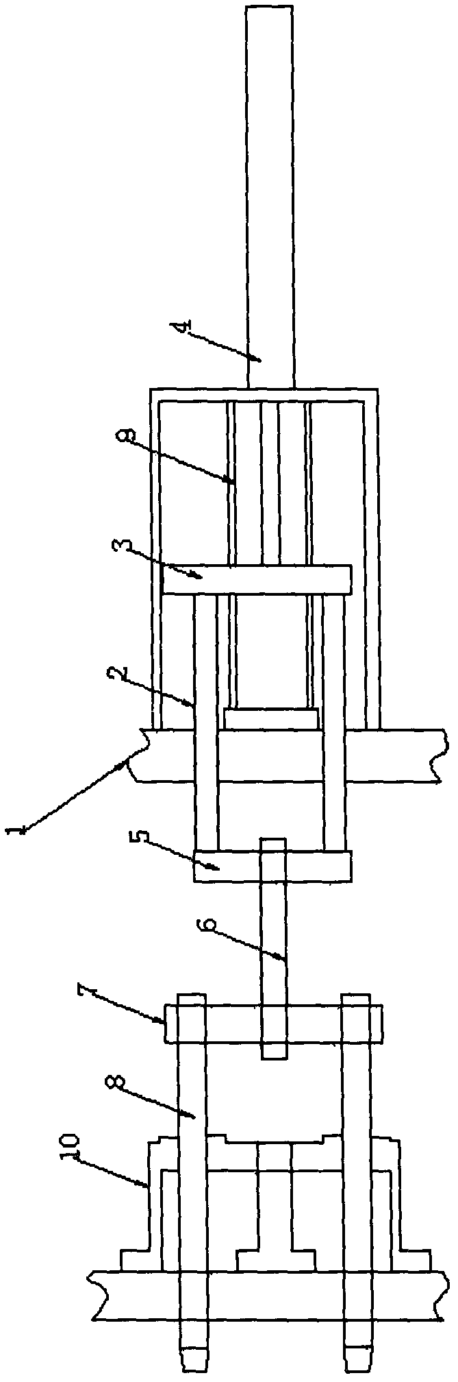
[0010] Such as figure 1 As shown, the pitch adjustment mechanism of the spring machine includes a frame 1, the frame 1 is provided with a driving part 4, the first-stage push rod 2 is arranged on the first-stage push plate 3, and the first-stage push plate 3 is connected to the drive The parts 4 are connected, the first stage push rod 2 is connected with the second stage push plate 5, the second stage push rod 6 is arranged on the second stage push plate 5, the third stage push plate 7 is connected with the second stage push rod 6, The third stage push rod 8 is located on the third stage push rod 7 .
[0011] The frame 1 is provided with a guide column of the first-stage push plate 3 , and the third-stage push rod 7 is also arranged on the frame 1 through a guide member 10 .
[0012] The driving part 4 is an oil cylinder.
PUM
 Abstract
Description
Claims
Application Information