Comparator and a/d converter

a converter and converter technology, applied in the field of comparator and a/d converter, can solve the problems of increasing the resolution of the a/d converter, increasing the level of required specifications, increasing the power consumption and occupied area, etc., and achieving the effect of not deteriorating the comparator precision

Active Publication Date: 2009-07-16
SOCIONEXT INC
View PDF5 Cites 14 Cited by
  • Summary
  • Abstract
  • Description
  • Claims
  • Application Information

AI Technical Summary

Benefits of technology

[0035]As described above, according to the present invention, the comparison precision does not deteriorate even if the frequency of the clock signal and the frequency of the analog input signal are high. Therefore, it is possible to expand the frequency of the clock signal and the frequency of the analog input signal.

Problems solved by technology

However, there is a disadvantage that in order to increase the resolution of the A / D converter by one bit, it is necessary to double the number of differential amplifiers and the number of comparators, thus increasing the power consumption and the occupied area.
Moreover, there is another disadvantage that increasing the resolution of the A / D converter increases the level of required specifications such as the offset error and the gain of the differential amplifiers, and the offset error and the comparison precision of the comparators.
However, as with the conventional A / D converter 1400, there is a disadvantage that in order to increase the resolution of the A / D converter by one bit, it is necessary to double the number of comparators, thus increasing the power consumption and the occupied area.
Moreover, as with the conventional A / D converter 1400, there is another disadvantage that increasing the resolution of the A / D converter increases the level of required specifications such as the offset error and the comparison precision of the comparators.

Method used


Image

  • Comparator and a/d converter
  • Comparator and a/d converter
  • Comparator and a/d converter

Examples


embodiment 1

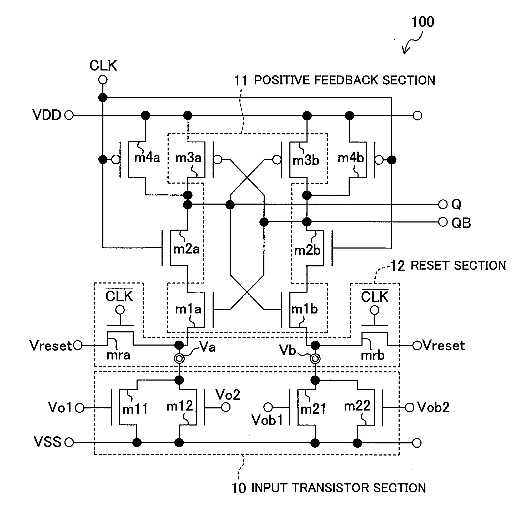
[0074]FIG. 1 shows an exemplary configuration of a dynamic-type comparator 100 of Embodiment 1.

[0075]Referring to the figure, the comparator 100 includes an input transistor section 10 including NMOS transistors m11, m12, m21 and m22, and a positive feedback section (cross-coupled inverter latch section) 11 including NMOS transistors m1a and m1b and PMOS transistors m3a and m3b, wherein an output terminal QB is connected to the gate terminals of m1a and m3a and the drain terminal of m3b of the positive feedback section 11, and an output terminal Q is connected to the gate terminals of the transistors m1b and m3b and the drain terminal of the transistor m3a of the positive feedback section 11. Referring to FIG. 1, an NMOS transistor m2a functioning as a switch in synchronism with the clock signal CLK is connected between the drain terminal of the NMOS transistor m1a and the drain terminal of the PMOS transistor m3a, and an NMOS transistor m2b functioning as a switch in synchronism wi...

embodiment 2

[0087]FIG. 4 shows an exemplary configuration of a dynamic-type comparator 400 of Embodiment 1. The comparator 400 includes an input transistor section including NMOS transistors m11, m12, m21 and m22, and a positive feedback section (cross-coupled inverter latch section) including NMOS transistors m1a and m1b and PMOS transistors m3a and m3b, wherein an output terminal QB is connected to the gate terminals of the transistors m1a and m3a and the drain terminal of the transistor m3b of the positive feedback section, and an output terminal Q is connected to the gate terminals of the transistors m1b and m3b and the drain terminal of the transistor m3a of the positive feedback section. An NMOS transistor m2a functioning as a switch in synchronism with the clock signal CLK is connected between the drain terminal of the NMOS transistor m1a and the drain terminal of the PMOS transistor m3a, and an NMOS transistor m2b functioning as a switch in synchronism with CLK is connected between the ...

embodiment 3

[0096]FIG. 5 shows an exemplary configuration of a dynamic-type comparator 500 of Embodiment 3. The comparator 500 includes an input transistor section including NMOS transistors m11, m12, m21 and m22, and a positive feedback section (cross-coupled inverter latch section) including NMOS transistors m1a and m1b and PMOS transistors m3a and m3b, wherein an output terminal QB is connected to the gate terminals of the transistors m1a and m3a and the drain terminal of the transistor m3b of the positive feedback section, and an output terminal Q is connected to the gate terminals of the transistors m1b and m3b and the drain terminal of the transistor m3a of the positive feedback section. An NMOS transistor m2a functioning as a switch in synchronism with the clock signal CLK is connected between the drain terminal of the NMOS transistor m1a and the drain terminal of the PMOS transistor m3a, and an NMOS transistor m2b functioning as a switch in synchronism with CLK is connected between the ...


PUM


Abstract

A comparator used in a parallel-type A / D converter, wherein a comparator 100 includes reset transistors mra and mrb. When the comparator 100 is in the Reset state, the inverted signal / CLK of the clock signal is given to the PMOS reset transistors mra and mrb so as to forcibly reset both of the voltages at two internal nodes Va and Vb being a differential pair to a predetermined reset voltage by the reset transistors mra and mrb. The inverted signal / CLK of the clock signal is produced with a predetermined delay. Thus, when the comparator 100 is in the Reset state, the point in time at which to cancel the reset of the internal nodes Va and Vb is delayed from that at which the comparator performs a comparison operation. Therefore, even if the frequency of the clock signal and the frequency of the analog input signal are high, the voltages at the internal nodes forming a differential pair are well-balanced when the comparator is in the Reset state, thus improving the voltage comparison precision.

Description

TECHNICAL FIELD[0001]The present invention relates to a comparator for receiving a plurality of differential voltage pairs and performing a comparison operation, in synchronism with a clock signal, on each differential voltage of the plurality of differential voltage pairs, and an A / D converter for converting an analog signal to a digital signal, or more particularly, an A / D converter having a parallel-type configuration.BACKGROUND ART[0002]In recent years, with the increase in the speed of information communications, the increase in the speed of an optical disc pick-up and the increase in the capacity, there is an increasing demand for an A / D converter with a high speed and a wide input bandwidth, which also has a reduced area and a reduced power consumption in order to reduce the cost.[0003]FIG. 14 shows a configuration of a conventional parallel-type A / D converter 1400. A high-speed analog / digital conversion was realized by using this A / D converter.[0004]The A / D converter 1400 in...

Claims


Application Information

Patent Timeline
Patent Type & Authority Applications(United States)
IPC IPC(8): H03M1/12H03K5/22
CPCH03K5/2481H03M1/362H03M1/204H03M1/0607
Inventor NAKA, JUNICHISUSHIHARA, KOJI
Owner SOCIONEXT INC
Why Eureka
Try Eureka