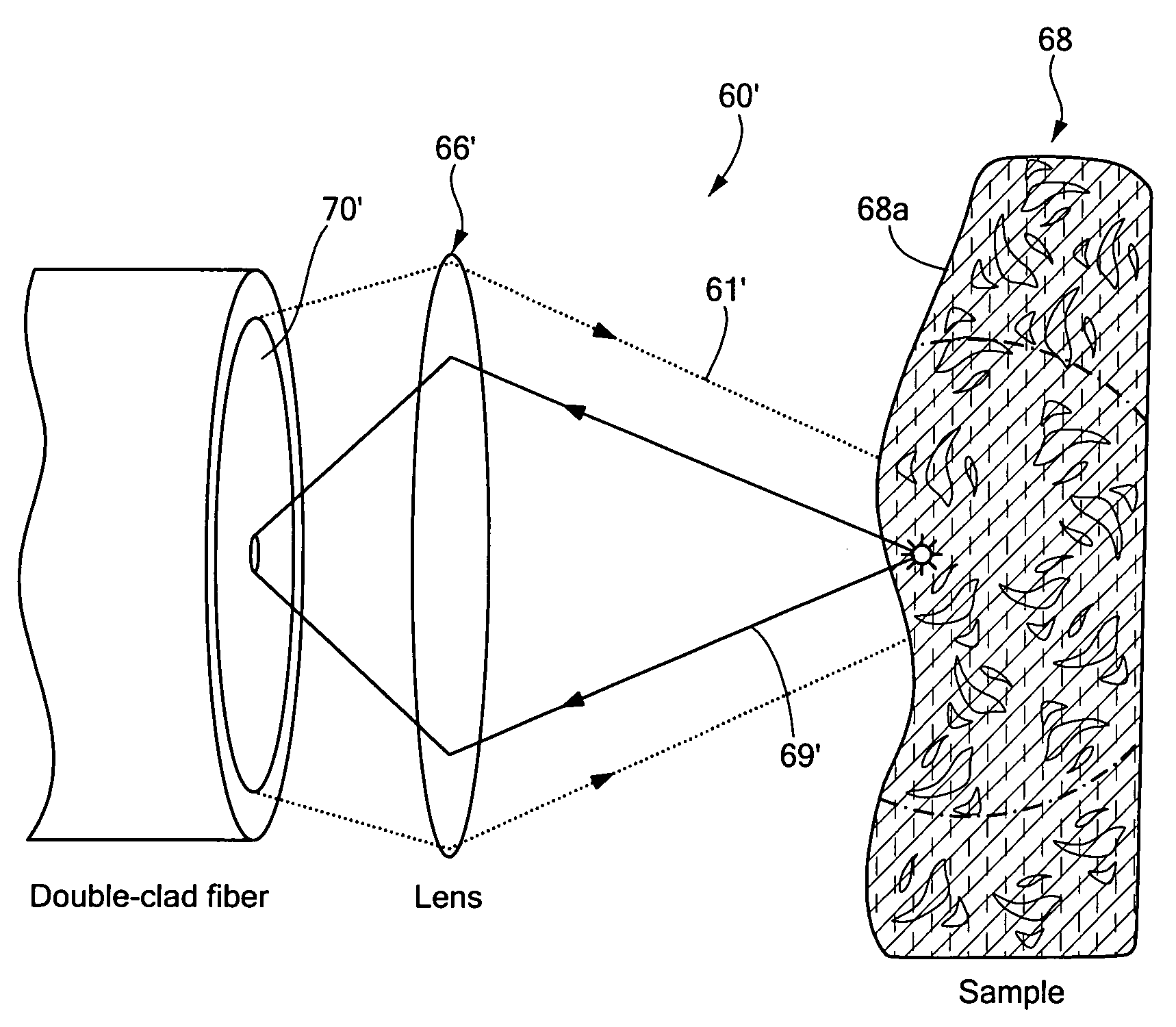
[0009]In accordance with the present invention, a method for imaging a sample through an optical fiber having a core and at least one cladding region includes (a) transmitting a first propagating mode of light through the core of the optical fiber toward the sample and (b) collecting scattered light from the sample in at least a first one of the at least one cladding regions of the optical fiber. Using the fiber's core for illumination and the inner clad for signal collection reduces image speckle, improves depth of field and increases signal efficiency (i.e. allows the collection of more light). Fiber core for illumination and inner clad for signal collection increases depth of field because an increase in the diameter of the collection aperture increases the depth of field and increased diameter of collection aperture increases the amount of light that can be detected through that aperture. This of course assumes that the collection aperture diameter of the inner cladding is greater than that of the core. A modeling of this effect is represented in FIGS. 3B and 3C below
[0010]In accordance with a further aspect of the present invention, a method for imaging a sample through an optical fiber having a core and at least one cladding region includes (a)transmitting a first propagating mode of light through at least one of the at least one cladding regions toward the sample and (b) collecting scattered light from the sample in a core of the optical fiber. With this particular arrangement, a technique in which inner cladding of a double clad fiber (or multi-clad fiber) can be used to deliver the illumination light, and the core can be used to collect the light. The large, high numerical aperture (NA), inner clad allows for efficient coupling of illumination light that is spatially incoherent from light sources such as Halogen, Mercury or Xenon lamps. This approach maintains the reduced image speckle due to the multiple illumination angles and the large depth of field, at the expense of a subtle drop in image resolution. The signal collection efficiency is lower compared to the core-illumination clad-collection scheme discussed above, but the increase in excitation light can compensate for that by increasing the signal.
[0012]With this particular arrangement, an imaging system which utilizes the core of a fiber for illumination and the inner clad of the fiber for signal collection is provided. This results in a technique which reduces image speckle and provides improved depth of field and increased signal efficiency. Using the fiber's core for illumination and the inner clad for signal collection reduces image speckle, improves depth of field and increases signal efficiency. It should, however, be appreciated that the double-clad fiber can be used by taking the opposite approach: the inner clad can be used to deliver the illumination light, and the core to collect the light. The large, high numerical aperture (NA), inner clad allows for efficient coupling of illumination light that is spatially incoherent from light sources. This approach maintains the reduced image speckle due to the multiple illumination angles and the large depth of field, at the expense of a subtle drop in image resolution. The signal collection efficiency is lower compared to the core-illumination clad-collection scheme discussed earlier, but the increase in excitation light can compensate for that by increasing the signal. In some embodiments, it may be advantageous to process information collected through both the core and the cladding regions regardless of whether the illumination light, is delivered through the core or the cladding. By separately collecting information through both the core and the cladding, information provided from one source (e.g. thought the core) can be used to enhance the information collected from the other (e.g. through the cladding). The information collected through each channel (e.g. the core-transmit / core-collection channel, the core-transmit / cladding-collection channel) can be processed and combined to provide information concerning the sample which is not readily available or apparent from the information collected in any single channel. Since the light returned through the core has higher transverse spatial frequencies than light collected through the cladding, one example of such combination of core and cladding light would be to utilize the information obtained through the core to sharpen the information received through the cladding. Additionally, light detected from the core is single mode which enables three-dimensional or phase sensitive information to be obtained when used in conjunction with an interferometer. This information can be utilized to enhance the incoherent information received by the inner cladding in the form of an overlay or pseudocolor representation of phase or three-dimensional information superimposed onto the spatially incoherent information provided by light detected through the inner cladding.
[0014]In summary, the use of a double-clad optical fiber in an imaging system provides many benefits to single optical fiber based imaging. In addition to improved image quality, utilization of a double clad fiber enables implementation of single mode illumination with both single- and multi-mode detection, by incorporating a detection beam-splitter with spatial filtering. This enhancement can enable dual-mode imaging where the multi-mode detection can be used to obtain the diffuse endoscopy image and the single-mode detection could be used for interferometric detection such as that employed by three-dimensional spectrally-encoded endoscopy.
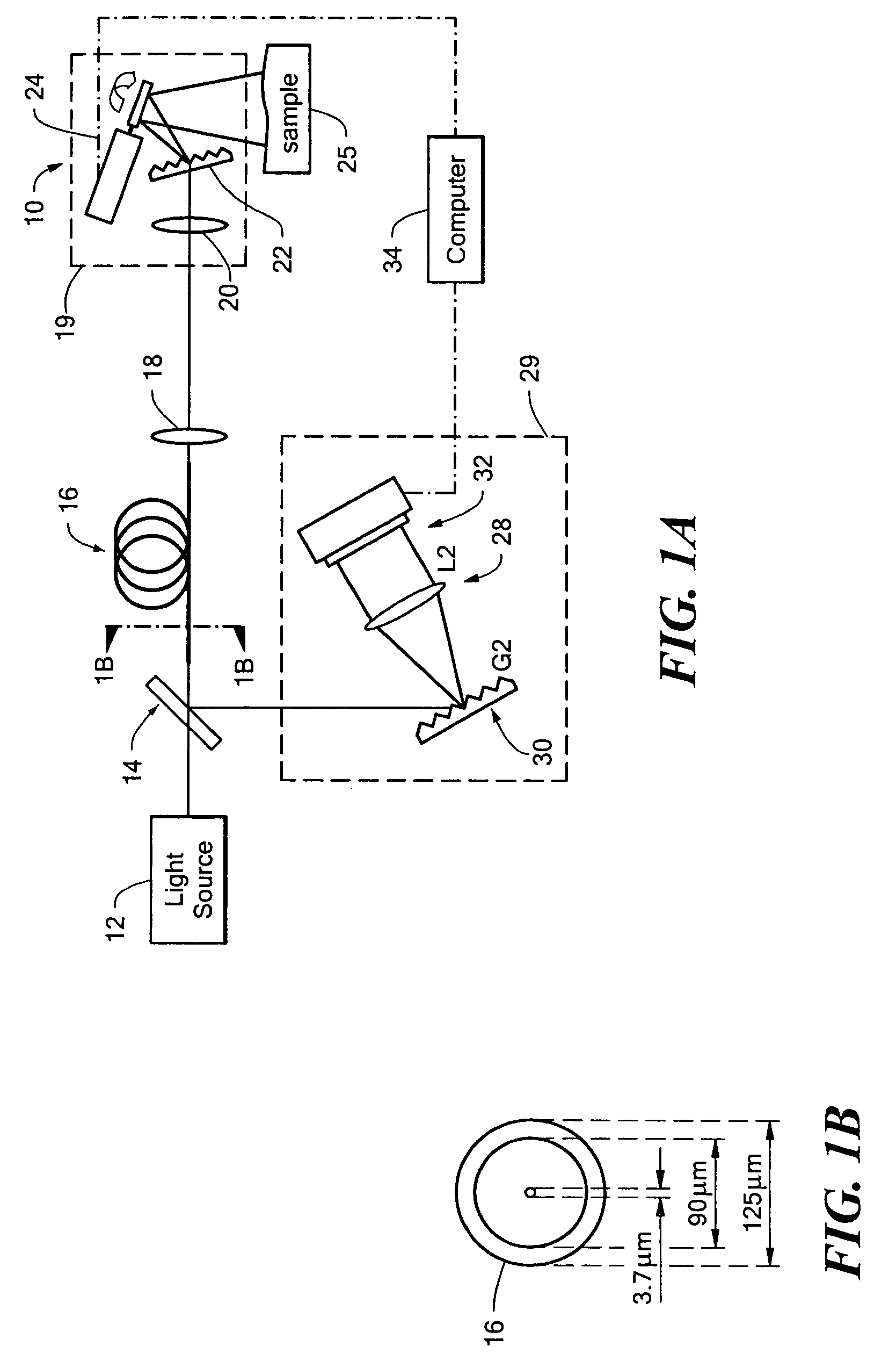
[0015]It has been found that double-clad optical fiber can be used to obtain speckle-free, signal-efficient spectrally-encoded imaging. By coupling the illuminating broadband light into the fiber's core only, and collecting the reflected light with the inner cladding (a configuration which is referred to herein as single mode-multimode or SM-MM), it is possible to combine the benefits of single-mode illumination with the advantages of multi-mode signal collection.

