Imaging system and related techniques

a technology of image resolution and imaging system, applied in the field of optical imaging, can solve the problems of subtle drop in image resolution, and achieve the effect of improving image quality

Active Publication Date: 2006-01-19
THE GENERAL HOSPITAL CORP
View PDF99 Cites 46 Cited by
  • Summary
  • Abstract
  • Description
  • Claims
  • Application Information

AI Technical Summary

Benefits of technology

[0014] In summary, the use of a double-clad optical fiber in an imaging system provides many benefits to single optical fiber based imaging. In addition to improved image quality, utilization of a double clad fiber enables implementation of single mode illumination with both single- and multi-mode detection, by incorporating a detection beam-splitter with spatial filtering. This enhancement can enable dual-mode imaging where the multi-mode detection can be used to obtain the diffuse endoscopy image and the single-mode detection could be used for interfe

Problems solved by technology

This approach maintains the reduced image speckle due to the multiple illumination angles and the large depth of field, at the expense of a subtle drop in image resolution.

Method used


Image

  • Imaging system and related techniques
  • Imaging system and related techniques
  • Imaging system and related techniques

Examples


Embodiment Construction

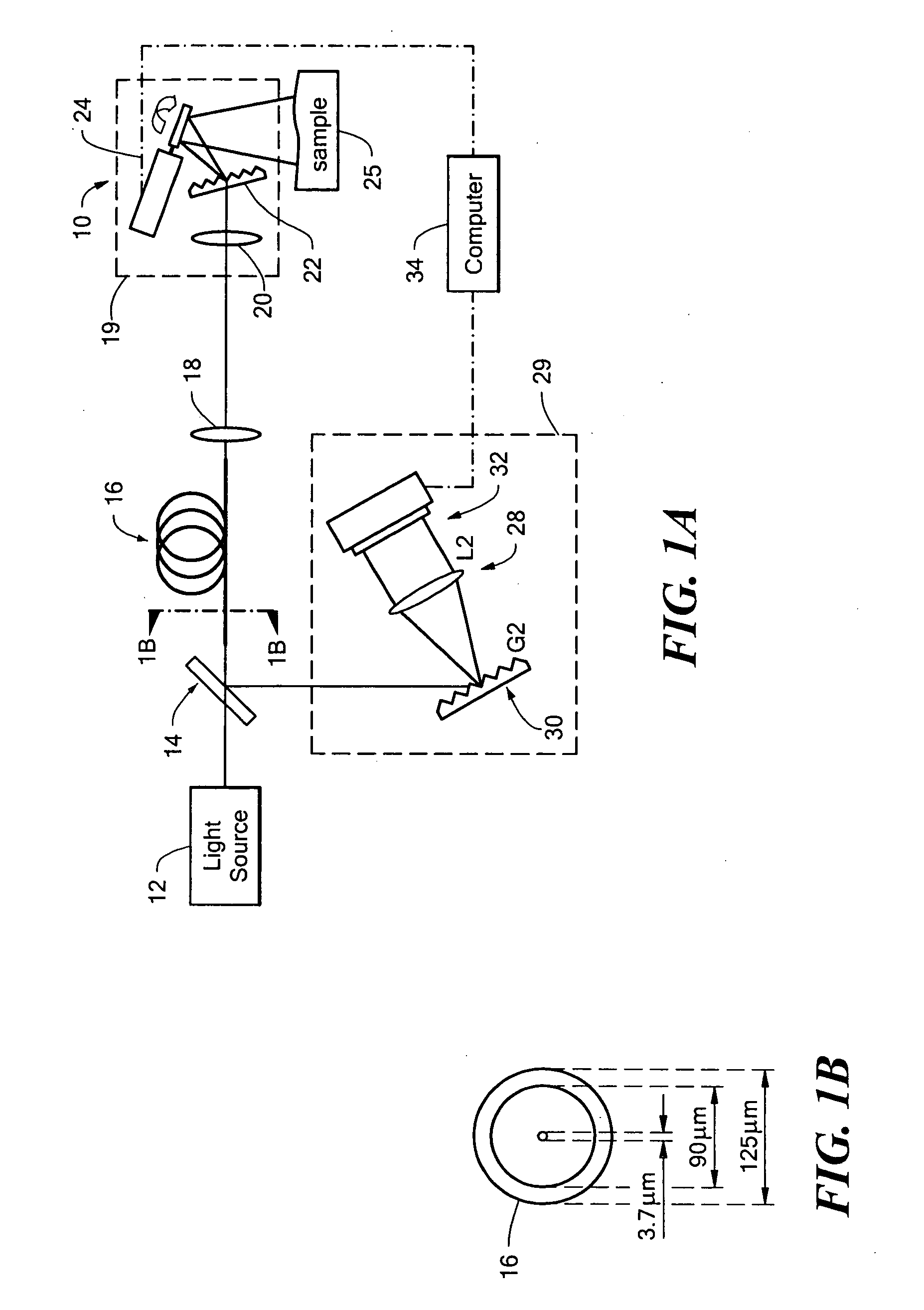
[0030] Referring now to FIG. 1, an optical system 10 for spectrally-encoded imaging with a double-clad fiber includes a broadband light source 12 which transmits light to a beam splitter (BS) 14. A first portion of the light is directed toward a double clad fiber (DCF) 16. The light propagates through the DCF 16 and through a collimating lens 18 to a miniature imaging probe 19.

[0031] In FIG. 1, the miniature imaging probe 19 is simulated using a compact lens grating design provided from a lens 20 and a grating 22. A galvanometric optical scanner 24 controlled by a processor 34 to performs slow axis scanning. The scanner directs the light toward a surface of a sample 25.

[0032] Light scattered from the sample 25 is coupled into the inner cladding or core or both the inner cladding and core of the DCF 16 and deflected by the beam splitter 14 (BS) to a spectrometer 29. In this exemplary embodiment, spectrometer 29 includes a lens 28, a diffraction grating 30, and a high-speed line-sca...


PUM


Abstract

A method and apparatus for imaging using a double-clad fiber is described.

Description

CROSS-REFERENCE TO RELATED APPLICATIONS [0001] This application claims the benefit under 35 U.S.C. §119(e) of Provisional Patent Application No. 60 / 585,065 filed on Jul. 2, 2004, which application is hereby incorporated herein by reference in its entirety.STATEMENTS REGARDING FEDERALLY SPONSORED RESEARCH [0002] Not applicable. FIELD OF THE INVENTION [0003] This invention relates generally optical imaging and more particularly to a method and apparatus for performing three-dimensional surface measurements. BACKGROUND OF THE INVENTION [0004] As is known in the art, fiber optic endoscopy is typically conducted by transmitting an image through an array of fibers often referred to as a fiber bundle. While successful for a variety of medical and non-medical applications, utilization of an array of fibers to form the image imposes constraints on the cost, diameter, and flexibility of the imaging device. [0005] In an attempt to overcome these drawbacks, multiple approaches employing a singl...

Claims


Application Information

Patent Timeline
IPC IPC(8): G02B6/06G01B9/04G01B11/00
CPCG02B6/02042G02B6/03605G02B6/03622G02B6/03638G02B6/4298G02B6/036G02B23/26G02B26/10G02B27/48G01N21/47G02B6/02G02B23/2469G01N21/474
Inventor BOUMA, BRETT E.TEARNEY, GUILLERMO J.YELIN, DVIR
Owner THE GENERAL HOSPITAL CORP
Why Eureka
Try Eureka