

Optical image capturing lens assembly
- Summary
- Abstract
- Description
- Claims
- Application Information
AI Technical Summary
Benefits of technology
Problems solved by technology
Method used
Image

Examples
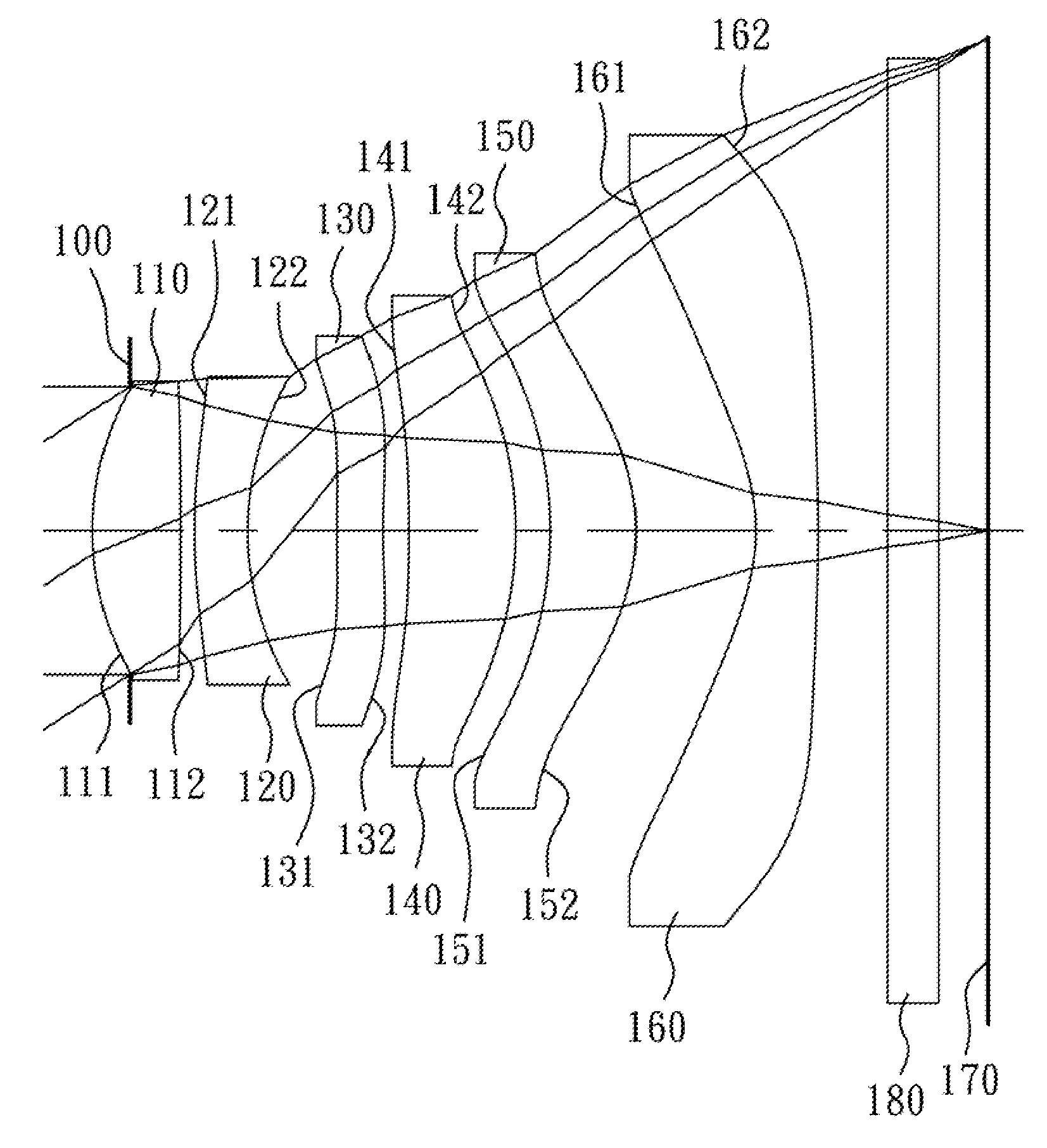
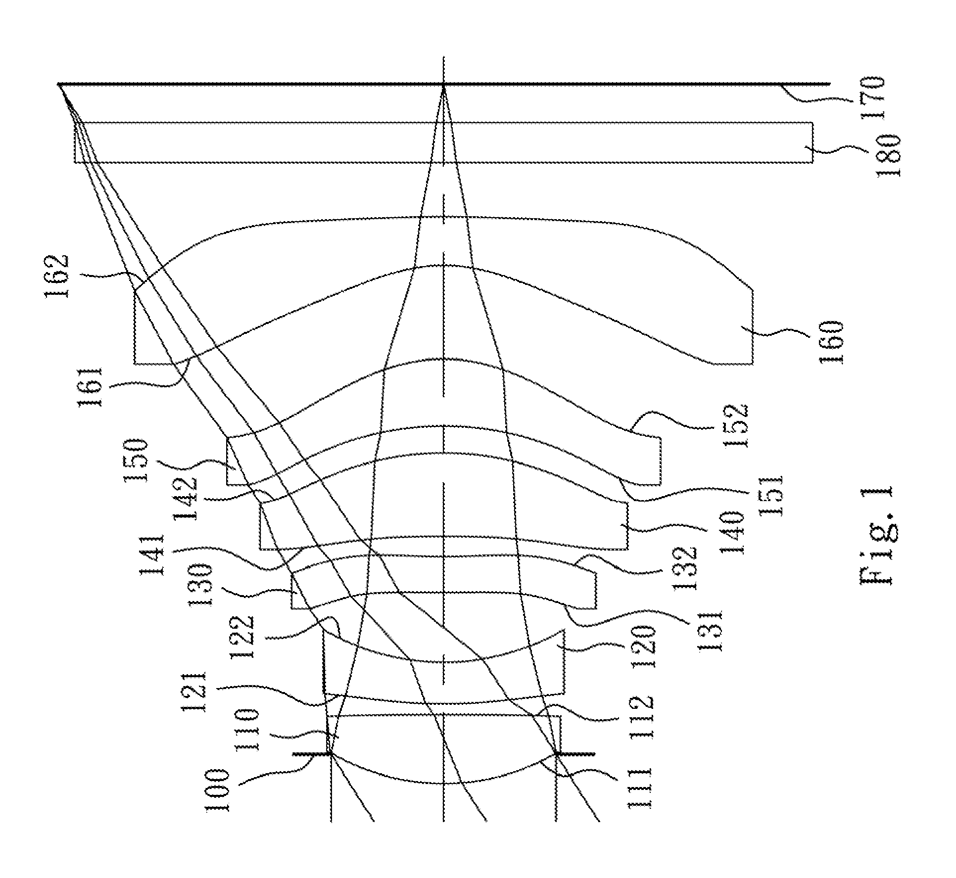
first embodiment
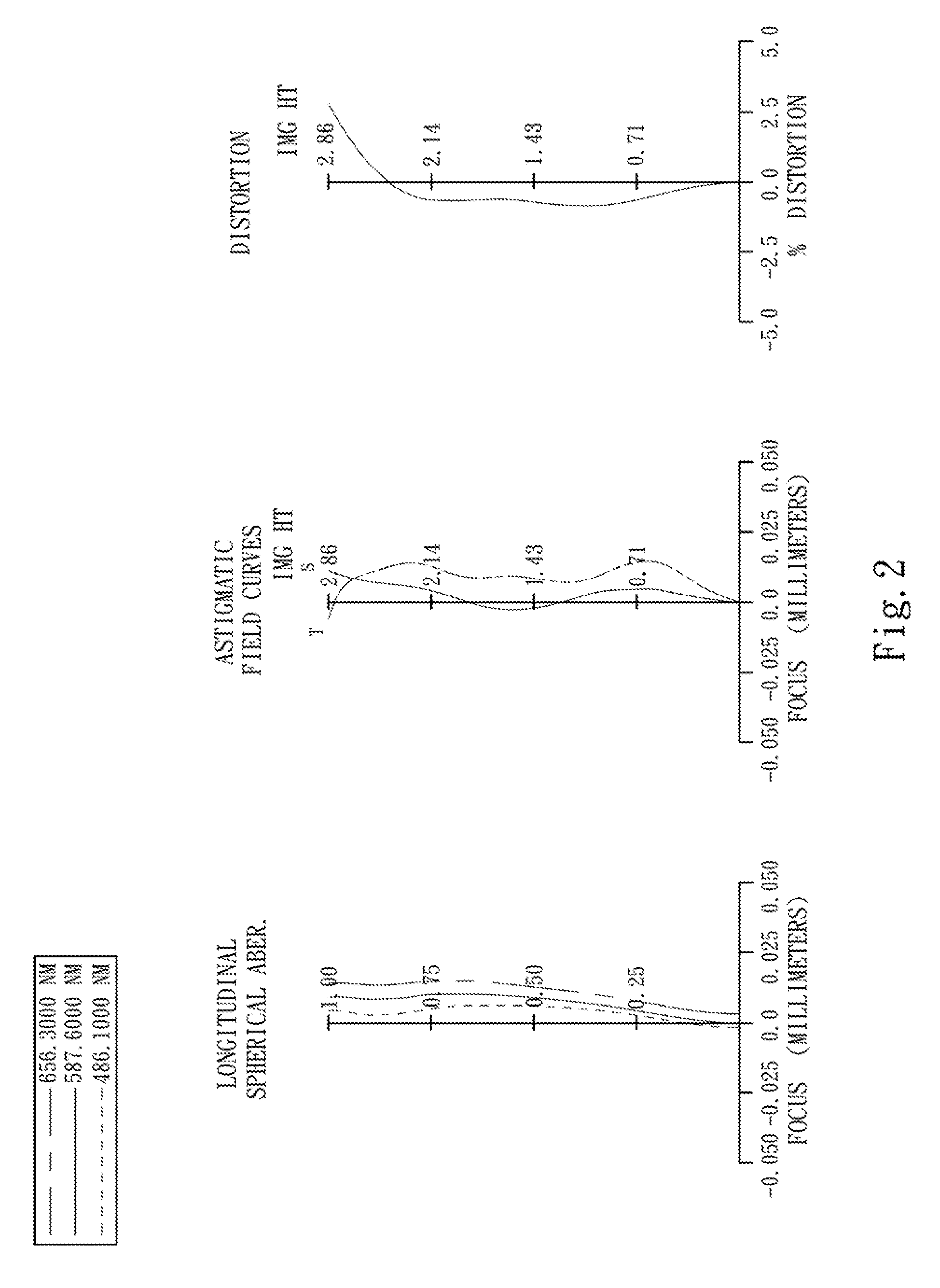
[0075]The equation of the aspheric surface profiles of the aforementioned lens elements of the first embodiment is expressed as follows:
X(Y)=(Y2 / R) / (1+sqrt(1-(1+k)×(Y / R)2))+∑i(Ai)×(Yi)
[0076]where:
[0077]X is the height of a point on the aspheric surface spaced at a distance Y from the optical axis relative to the tangential plane at the aspheric surface vertex;
[0078]Y is the distance from the point on the curve of the aspheric surface to the optical axis;
[0079]R is the curvature radius of the lens elements;
[0080]k is the conic coefficient; and
[0081]Ai is the i-th aspheric coefficient.
[0082]In the optical image capturing lens assembly according to the first embodiment, when a focal length of the optical image capturing lens assembly is f, an f-number of the optical image capturing lens assembly is Fno, and a half of the maximal field of view is HFOV, these parameters have the following values:
[0083]f=4.35 mm;
[0084]Fno=2.60; and
[0085]HFOV=32.6 degrees.
[0086]In the optical image capturi...
second embodiment
[0107]The detailed optical data of the second embodiment are shown in Table 3 and the aspheric surface data are shown in Table 4 below.
TABLE 32nd Embodimentf = 4.43 mm, Fno = 2.60, HFOV = 32.6 deg.FocalSurface #Curvature RadiusThicknessMaterialIndexAbbe #length0ObjectPlanoInfinity1Ape.Plano−0.265 Stop2Lens 1 1.490210 (ASP)0.577Plastic1.53055.82.553−12.436800 (ASP) 0.1644Lens 2−7.977300 (ASP)0.264Plastic1.63423.8−3.105 2.643620 (ASP)0.3136Lens 3 5.555600 (ASP)0.385Plastic1.58330.25.777−8.333300 (ASP)0.2648Lens 4−2.393140 (ASP)0.353Plastic1.54455.9102.029−2.413490 (ASP)0.25610Lens 5−4.496300 (ASP)0.500Plastic1.53055.84.8611−1.700290 (ASP)0.49012Lens 6−1.096720 (ASP)0.365Plastic1.53055.8−2.4713−7.575800 (ASP)0.40014IR-filterPlano0.300Glass1.51764.2—15Plano0.28916ImagePlano—Note:Reference wavelength (d-line) is 587.6 nm.
TABLE 4Aspheric CoefficientsSurface #234567k =−4.76032E−01−1.00000E+00−5.91073E+00−1.00000E+002.57359E+00−1.00000E+00A4 =2.54298E−022.52926E−02−4.87798E−02−8.08942E−...
third embodiment
[0117]The detailed optical data of the third embodiment are shown in Table 5 and the aspheric surface data are shown in Table 6 below.
TABLE 53rd Embodimentf = 4.36 mm, Fno = 2.60, HFOV = 32.6 deg.FocalSurface #Curvature RadiusThicknessMaterialIndexAbbe #length0ObjectPlanoInfinity1Ape.Plano−0.220 Stop2Lens 1 1.683250 (ASP)0.531Plastic1.53055.82.793−10.792800 (ASP) 0.1224Lens 2−83.450000 (ASP) 0.277Plastic1.63323.4−4.395 2.878170 (ASP)0.3686Lens 312.864800 (ASP)0.387Plastic1.54455.96.077−4.398500 (ASP)0.1508Lens 4−1.861400 (ASP)0.615Plastic1.54455.9−14.579−2.715700 (ASP)0.20010Lens 513.029800 (ASP)0.653Plastic1.53055.83.8711−2.389790 (ASP)0.51912Lens 6−1.043310 (ASP)0.365Plastic1.53055.8−2.3313−7.575800 (ASP)0.40014IR-filterPlano0.300Glass1.51764.2—15Plano0.28516ImagePlano—Note:Reference wavelength (d-line) is 587.6 nm.
TABLE 6Aspheric CoefficientsSurface #234567k =−4.33527E−01−1.00000E+003.00000E+00−1.00000E+00−1.00000E+01−1.00000E+00A4 =2.59284E−024.03963E−02−6.77533E−02−1.14494E−...
PUM
 Abstract
Description
Claims
Application Information