Driving methods and circuit for bi-stable displays

a technology of bi-stable displays and driving methods, applied in the direction of instruments, static indicating devices, etc., can solve the problems of long-term image uniformity, approaches provide a practical solution, etc., and achieve the effect of optimal image quality and fast and most pleasing appearan

Inactive Publication Date: 2008-12-11
SIPIX IMAGING INC
View PDF82 Cites 184 Cited by
  • Summary
  • Abstract
  • Description
  • Claims
  • Application Information

AI Technical Summary

Benefits of technology

[0006]This disclosure is directed toward driving methods which are particularly suitable for electrophoretic (bi-stable) displays and which provide the fastest and most pleasing appearance to a desired image while maintaining optimal image quality over the life of an electrophoretic display device.

Problems solved by technology

These differences from pixel to pixel, in general, lead to long term issues with image uniformity.
Although attempts have been made previously to alleviate such problems with waveforms that have no DC bias or by use of clearing images to reduce non-uniformity, neither of these approaches provides a practical solution to such problems for the long term.

Method used


Image

  • Driving methods and circuit for bi-stable displays
  • Driving methods and circuit for bi-stable displays
  • Driving methods and circuit for bi-stable displays

Examples


example 1

One Time Display Implementation

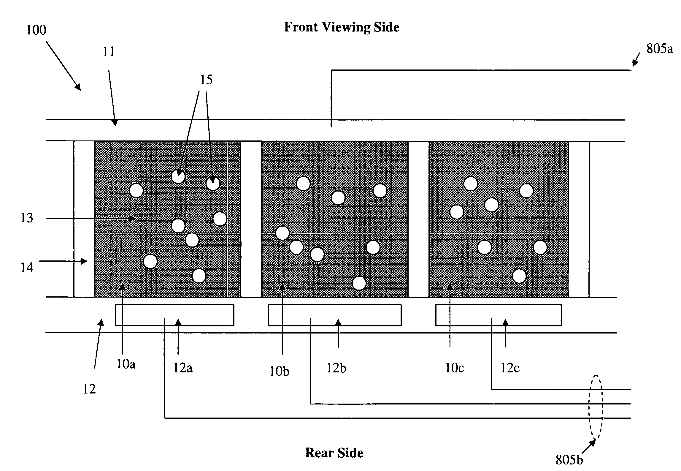
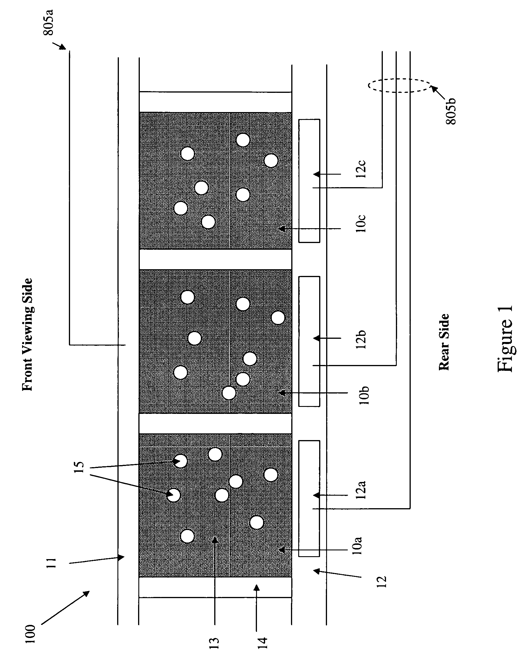
[0058]In this example, some of the images would be displayed on the electrophoretic display 100 only once. For one time display implementations, the displayed image on the electrophoretic display 100 is to be turned off or cleared after a pre-determined display period, for example, a one time password used in a smartcard application. After the onetime password is generated and displayed, the password image should be cleared for security reasons. In this implementation, the electrophoretic display 100 will be driven to the dark state and then wait for the next driving sequence.

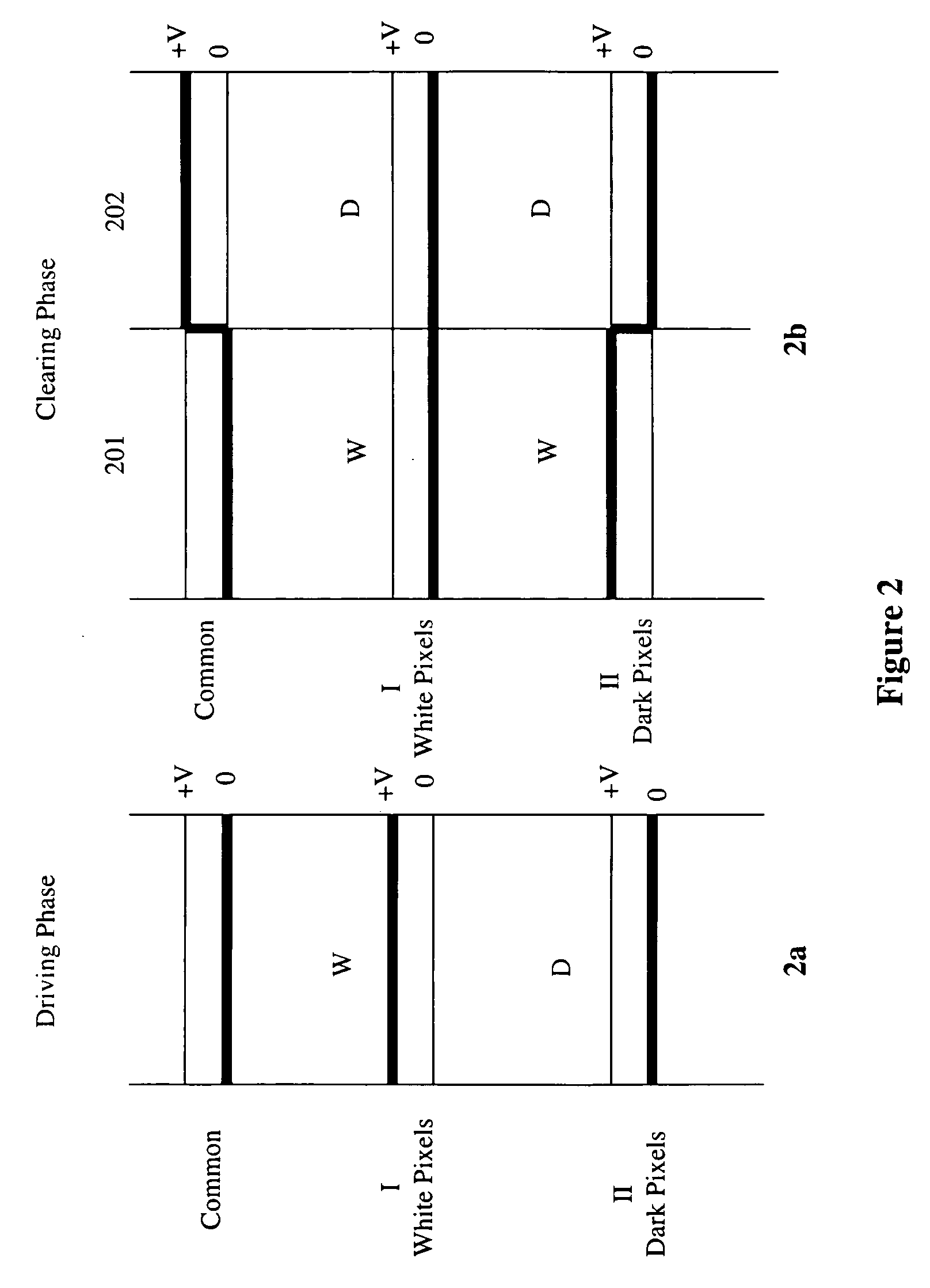
[0059]FIG. 2 illustrates one of the onetime display driving embodiments. In this embodiment, the initial color state or the “off” state of the electrophoretic display 100 is represented by the dark color state of the electrophoretic fluid 13 (display medium.) As depicted, the driving implementation has two phases, a driving phase and a clearing phase. The driving phase is shown in...

example 2

Alternative One Time Display Implementation

[0063]Experience has shown that if an electrophoretic display remains inactive for an extended period of time, the performance of transitioning from the dark state to the white state or vice versa may become degraded, and the dark state may have assumed a less than optimal charge value. FIG. 3 illustrates an alternative driving phase to that in FIG. 2 to address this issue. As shown in the FIG. 3, the driving phase in this alternative implementation has two driving frames, 301 and 302. For the common electrode 11 (FIG. 1) in this driving implementation, no voltage potential is applied in driving frame 301 and a voltage potential of +V is applied in driving frame 302. Waveform I drives pixels from the dark “off” state to the white state by applying across the display medium 13 a voltage potential of +V in frame 301 and no voltage potential in frame 302 and as a result, the pixels switch to the white state in frame 301 and remain in the white...

example 3

Multiple Message Display Implementation

[0065]An electrophoretic display may display multiple images sequentially. The multiple messages may be shown in sequence within a short period of time (e.g., 1-2 minutes) and the final message may remain for a longer period of time unless cleared or corrected. The multiple messages may be displayed one after another or the multiple messages may be a repeat of two or more messages, switching back and forth as driven by a microcontroller 800 (FIG. 8)

[0066]FIG. 4 depicts an example as to how multiple messages may be displayed in succession. In the sequence as shown, the “idle” time between messages is optional. The final message in the sequence may remain for a period of time, if needed. A corrective waveform may be applied between messages (not shown) or after the second message has been displayed to drive the white pixels to the dark state and provide DC balancing as briefly discussed above and discussed in more detail with respect to FIG. 5 be...


PUM


Abstract

The disclosure is directed toward driving methods and a driving circuit which are particularly suitable for bi-stable displays. In certain embodiments, methods provide the fastest and most pleasing appearance to the desired image while maintaining the optimal image quality over the life expectancy of an electrophoretic display device.

Description

BENEFIT CLAIM REFERENCE TO RELATED APPLICATIONS[0001]This application claims the benefit under 35 USC § 119(e) of provisional application 60 / 942,585, filed Jun. 7, 2007, the entire contents of which is hereby incorporated by reference for all purposes as if fully set forth herein.TECHNICAL FIELD[0002]The present disclosure relates to an electrophoretic display, and more specifically, to driving approaches and circuits for an electrophoretic display.BACKGROUND[0003]An electrophoretic display (EPD) is a non-emissive bi-stable output device which utilizes the electrophoresis phenomenon of charged pigment particles suspended in a dielectric fluid to display graphics and / or alphanumeric characters. The display usually comprises two plates with electrodes placed opposing each other. One of the electrodes is usually transparent. The dielectric fluid which includes a suspension of electrically charged pigment particles is enclosed between the two plates. When a voltage potential is applied ...

Claims


Application Information

Patent Timeline
Patent Type & Authority Applications(United States)
IPC IPC(8): G09G3/34
CPCG09G3/344G09G2320/0204G09G2320/0257G09G3/2003G09G3/34G09G2230/00G09G2320/0247
Inventor SPRAGUE, ROBERTHO, ANDREWCHEN, YAJUANZANG, HONGMEIWONG, JIALOCKWANG, CHEIN
Owner SIPIX IMAGING INC
Why Eureka
Try Eureka