Method and apparatus for three-dimensional microscopy with enhanced resolution

a three-dimensional optical microscopy and enhanced resolution technology, applied in the field of three-dimensional optical microscopy, can solve problems such as interference between two illumination beams at the focal plan

Inactive Publication Date: 2003-11-11
RGT UNIV OF CALIFORNIA
View PDF31 Cites 123 Cited by
  • Summary
  • Abstract
  • Description
  • Claims
  • Application Information

AI Technical Summary

Benefits of technology

Another object of the invention is to provide a method and apparatus for three-dimensional optical microscopy which does not cause unnecessary bleaching of samples.

Problems solved by technology

When the optical path lengths are balanced, the two illumination beams interfere at the focal plane of the two objectives.

Method used


Image

  • Method and apparatus for three-dimensional microscopy with enhanced resolution
  • Method and apparatus for three-dimensional microscopy with enhanced resolution
  • Method and apparatus for three-dimensional microscopy with enhanced resolution

Examples


Embodiment Construction

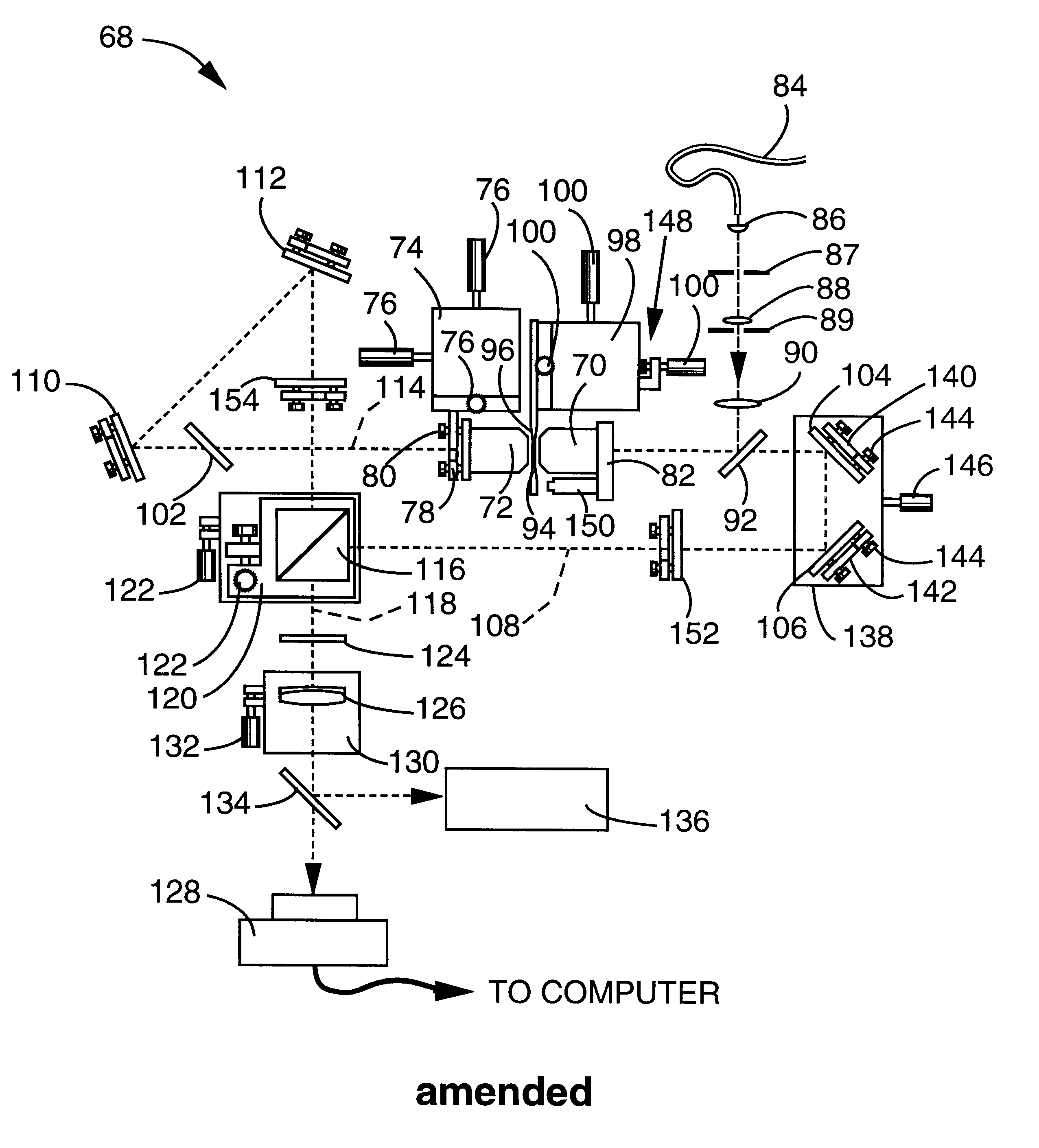
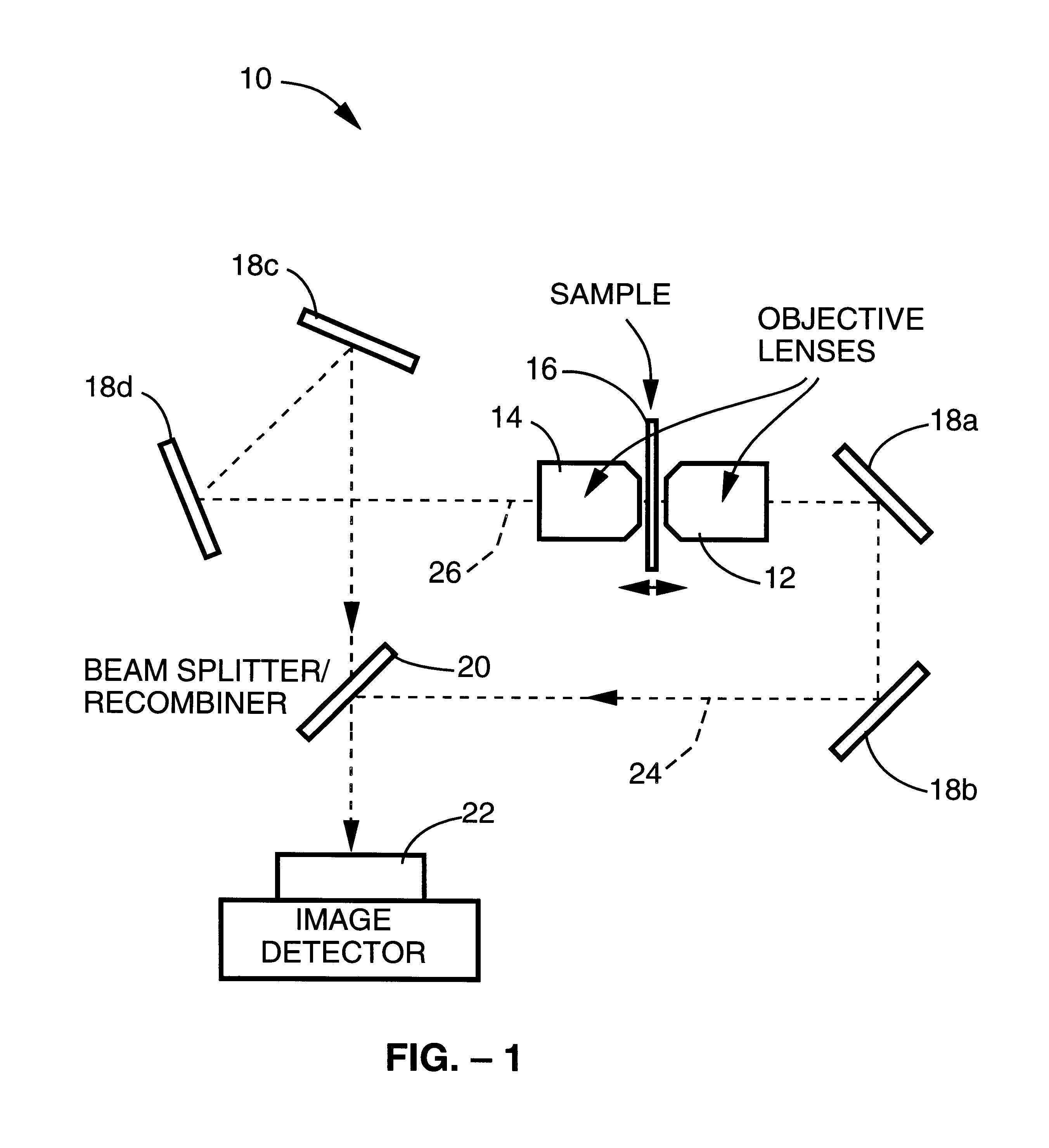
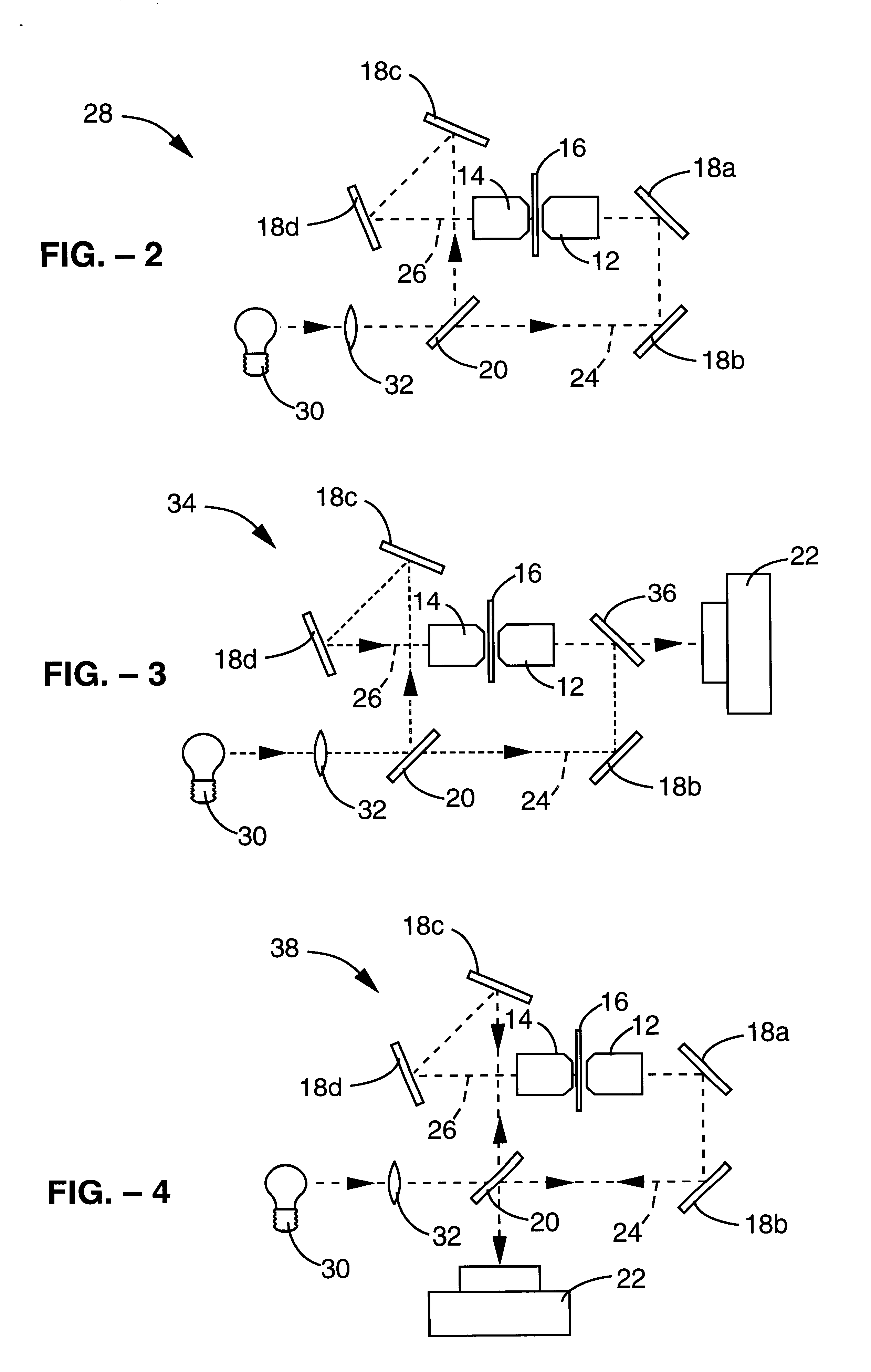
Referring more specifically to the drawings, for illustrative purposes the method and apparatus comprising the present invention and the underlying theory behind the invention are generally shown in FIG. 1 through FIG. 50. It will be appreciated that the apparatus of the invention may vary as to configuration and as to details of the parts, and that the method of the invention may vary as to the steps and their sequence, without departing from the basic concepts as disclosed herein.

Referring first to FIG. 1, a simplified schematic diagram of a microscope apparatus 10 in accordance with the first or I.sup.2 M embodiment of the present invention is generally shown. A first objective lens 12 and a second objective lens 14 are mounted about a sample 16, with objective lenses 12, 14 being focused, from opposite directions, on one and the same section or plane of sample 16. Sample 16 is preferably thin and mounted between two cover glasses. The observed light or images from first and seco...


PUM


Abstract

A method and apparatus for three dimensional optical microscopy is disclosed which employs dual opposing objective lenses about a sample and extended incoherent illumination to provide enhanced depth or Z.Iadd.-.Iaddend.direction resolution. In a first embodiment, observed light from both objective lenses are brought into coincidence on an image detector and caused to interfere thereon by optical path length adjustment. In a second embodiment, illuminating light from an extended incoherent light source is detected to the sample through both objective lenses and caused to interfere with a section of the sample by adjusting optical path lengths. Observed light from one objective lens is then recorded. In a third embodiment, which combines the first two embodiments, illuminating light from an extended incoherent light source is directed to the sample through both objective lenses and caused to interfere within a section of the sample by adjusting optical path lengths. The observed light from both lenses is caused to interfere on the image detector by the same optical path length adjustment. .Iadd.In a fourth embodiment of the invention, further spatial structure is introduced into the illumination light. Computational processing is used to enhance lateral or XY resolution as well as depth or Z resolution..Iaddend.

Description

.Iadd.CROSS-REFERENCE TO RELATED APPLICATIONSNot ApplicableREFERENCE TO A MICROFICHE APPENDIXNot Applicable.Iaddend.BACKGROUND OF THE INVENTION1. Field of the InventionThe present invention pertains generally to three-dimensional optical microscopy, and more particularly to a method and apparatus for three-dimensional optical microscopy which employs dual opposing objective lenses about a sample to obtain a high level of depth resolution.2. Description of the Background ArtOptical microscopy has experienced a remarkable renaissance in the medical and biological sciences during the last decade. The increased importance of optical microscopy has been due to new developments in fluorescent probe technology, and the availability of quantitative three-dimensional image data obtained through either computational deconvolution or scanning confocal microscopy.Optical microscopy offers several advantages over non-optical microscopy techniques. Use of optical microscopy allows viewing of livi...

Claims


Application Information

Patent Timeline
Patent Type & Authority Patents(United States)
IPC IPC(8): G02B21/18G02B21/22G01N21/27G02B21/00G02B21/06
CPCG02B21/22
Inventor GUSTAFSSON, MATS G. L.SEDAT, JOHN W.AGARD, DAVID A.
Owner RGT UNIV OF CALIFORNIA
Why Eureka
Try Eureka