Methods and Apparatus for Electrical Stimulation of Tissues Using Signals that Minimize the Effects of Tissue Impedance

Inactive Publication Date: 2009-01-29
HARGROVE JEFFREY B
View PDF28 Cites 121 Cited by
  • Summary
  • Abstract
  • Description
  • Claims
  • Application Information

AI Technical Summary

Benefits of technology

[0021]Also provided is a method for enhancing a body's own healing mechanisms. This method includes applying an electrical tissue stimulation signal to a subject suffering from one or more conditions selected from the group of conditions consisting of broken bones, injured tissues, post-surgical wounds, cuts, muscle pain associated with strains, and spasms.
[0022]Also provided is a method for improving a body's function. This method includes applying an electrical tissue stimulation signal to a subject, the signal configured and applied in such a way as to produce one or more effects selected from the group of effects consisting of reducing fatigue, increa

Problems solved by technology

Among other things, none of these patents discloses any consideration of the electrical nature of the tissues themselves, either at the macro level or at the basic cellular level, or of how tissue stimulation signals might be adapted to take into account that electrical nature.
Generally speaking, tissue is a relatively poor conductor of electricity due to high resistance

Method used


Image

  • Methods and Apparatus for Electrical Stimulation of Tissues Using Signals that Minimize the Effects of Tissue Impedance
  • Methods and Apparatus for Electrical Stimulation of Tissues Using Signals that Minimize the Effects of Tissue Impedance
  • Methods and Apparatus for Electrical Stimulation of Tissues Using Signals that Minimize the Effects of Tissue Impedance

Examples


first embodiment

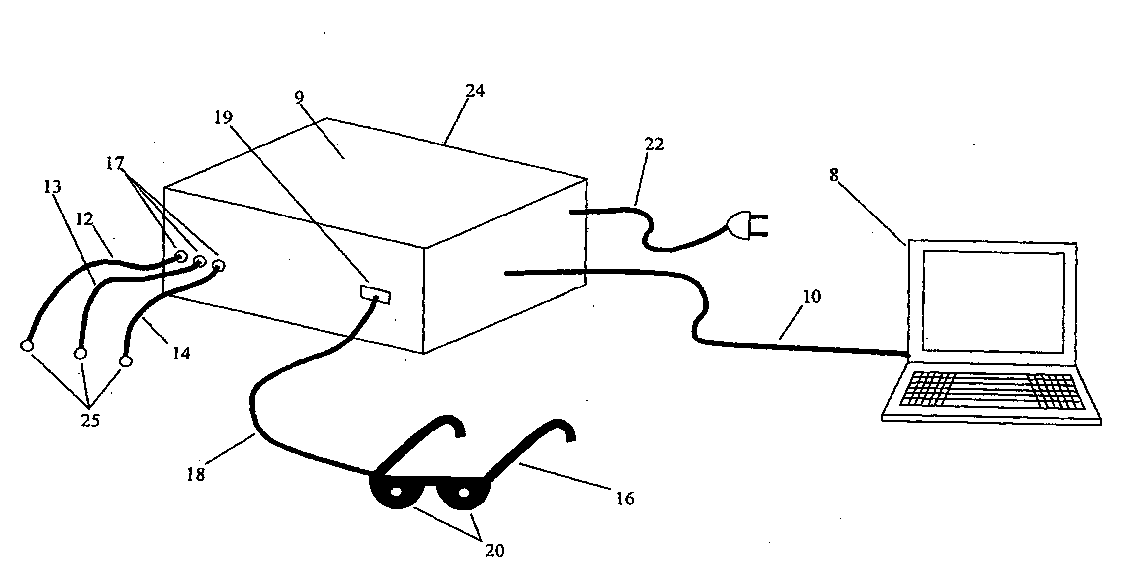
[0127]Various apparatus and circuits for creating and using an electrical signal for stimulating tissues such as an AMPWM signal are disclosed above. Here, an improved apparatus is provided, which provides for the generation of electrical tissue stimulation signals, such as AMPWM signals, that reduce tissue impedance and increase depth of signal penetration. a tissue stimulation apparatus for providing an electrical tissue stimulation signal that reduces tissue impedance and increases depth of signal penetration is shown in FIG. 12, as comprising an electrical stimulation device 101 and an external computing device 102 is provided. Power for the electrical stimulation device 101 may be provided by an external power source 105, such as a line connection or an adapter for providing a conditioned electrical source, electrically coupled to the electrical stimulation device 101 through a power connector 111.

[0128]Internally, the electrical stimulation device 101 may include a battery cha...

second embodiment

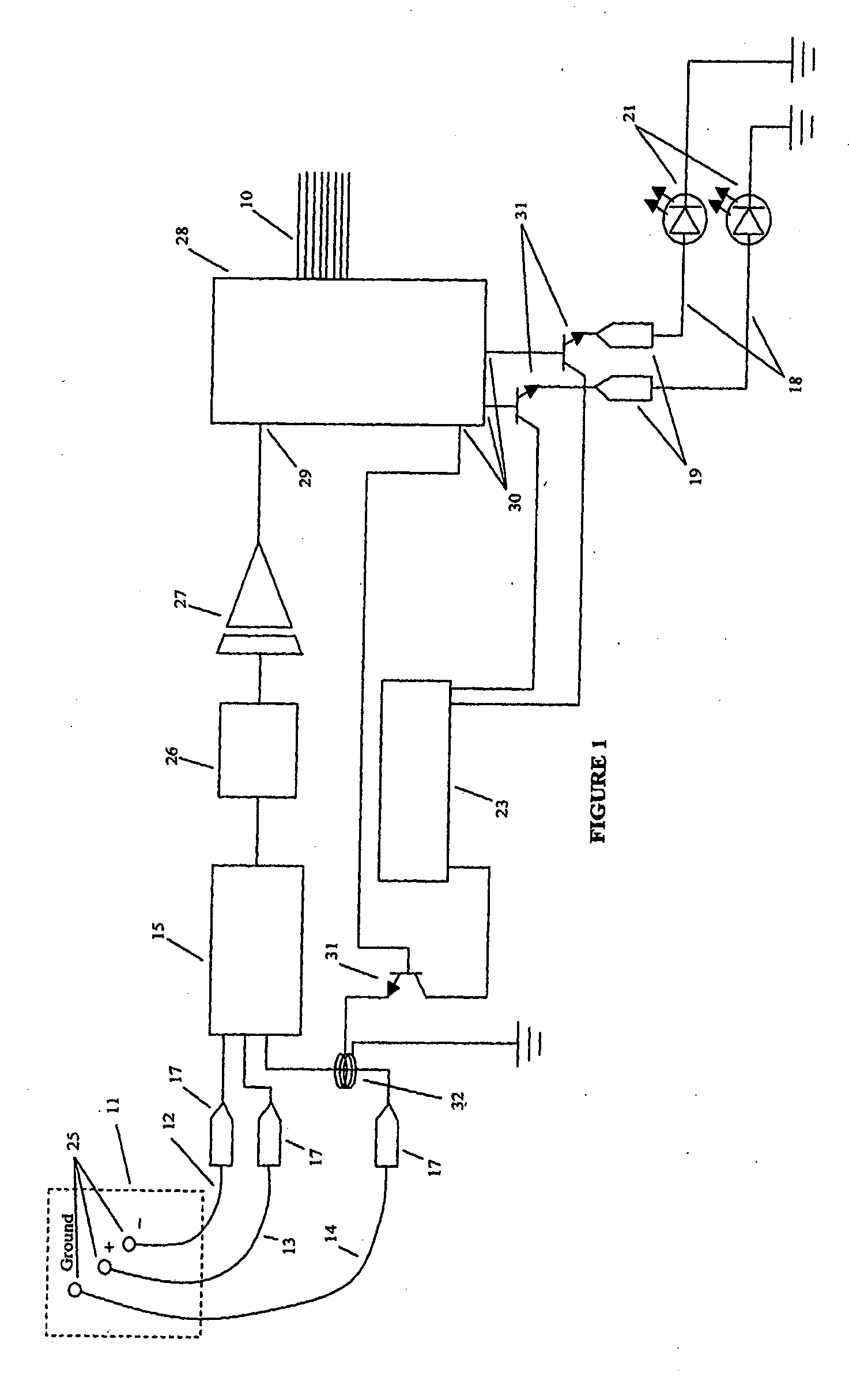
[0149]As shown in FIG. 14, tissue stimulation apparatus for providing an electrical tissue stimulation signal that reduces tissue impedance and increases depth of signal penetration is shown as comprising an electrical stimulation device 101 and a biopotential acquisition device that measures biopotential voltage in tissue to be stimulated. The biopotential acquisition device may include a biopotential amplifier module 127 comprising a biopotential amplifier 130, an impedance testing circuit 131, a second ground switching circuit 129 and a series of inductors 128 operatively coupled to conductors extending from the second ground switching circuit 129 and terminating at biopotential acquisition lead connectors 126 and thus operatively coupled to biopotential acquisition leads 125 coupled to the connectors 126. Further provisions may be made for any number of biopotential acquisition leads 125, and any number of ground leads 120, each lead 125, 120 including a sensor such as a surface...


PUM


Abstract

A tissue stimulation system that generates an electrical tissue stimulation signal configured to reduce tissue impedance and increase depth of signal penetration. The use of leads is dynamically controlled and altered between conducting biopotential voltages, conducting electrical tissue stimulation signals, and grounding, in response to a computational analysis of biopotential data acquired from a region of tissue to be stimulated.

Description

CROSS-REFERENCES TO RELATED APPLICATIONS[0001]This application is a Continuation-in-Part of U.S. patent application Ser. No. 11 / 490,255 which is a continuation of U.S. patent application Ser. No. 10 / 357,503 which claims priority in an earlier filed provisional application U.S. Ser. No. 60 / 353,234, filed on Feb. 4, 2002; this application also claims priority in and incorporates by reference U.S. Provisional Patent Application Ser. No. 60 / 963,486 filed 6 Aug. 2007, U.S. Provisional Patent Application Ser. No. 61 / 014,917 filed 19 Dec. 2007, and U.S. Provisional Patent Application Ser. No. 61 / 024,641 filed 30 Jan. 2008, and U.S. Provisional Patent Application Ser. No. 61 / 032,241 filed 28 Feb. 2008.BACKGROUND OF THE INVENTION[0002]1. Field of the Invention[0003]The present invention relates generally to the field of producing and applying electrical energy to tissues for the purpose of stimulating such tissues, and to therapeutic methods and apparatus. More specifically, the present inve...

Claims


Application Information

Patent Timeline
IPC IPC(8): A61N1/36A61B5/0402A61B5/0476A61B5/0488G06Q50/00
CPCA61B5/0402A61B5/048A61B5/04842A61B5/0488A61B5/053A61N1/37235A61B5/4519A61B5/6843A61B5/7257A61N1/36025A61N1/36082A61B5/145G16H50/70A61N1/36031A61N1/36034G16H40/63A61B5/318A61B5/374A61B5/369A61B5/377A61B5/378A61B5/389A61N1/37247
Inventor HARGROVE, JEFFREY B.
Owner HARGROVE JEFFREY B
Why Eureka
Try Eureka