Method and Related Communication Device for Enhancing Power Control Mechanism

a power control mechanism and communication device technology, applied in the field of wireless communication systems, can solve problems such as failure of uplink transmission, interference to other ues, and inability to deal with related tpc commands and transmission counters for redundancy versions, and achieve the effect of accurately applying and enhancing the power control mechanism

Inactive Publication Date: 2010-12-30
HTC CORP
View PDF6 Cites 158 Cited by
  • Summary
  • Abstract
  • Description
  • Claims
  • Application Information

AI Technical Summary

Benefits of technology

[0013]The disclosure therefore provides a method and related communication device for enhancing power control mechanism, which allows a mobile device capable of simultaneous transmission and reception with multiple communication signal sources to recognize which communication signal source a received power control configuration(s) corresponds to and to accurately apply the power control configuration(s) on corresponding communication signal source(s), so that the power control can be flexible and adaptive to different connections with the communication signal sources.

Problems solved by technology

Thus, in the abovementioned colliding situation, the UE may not perform the uplink transmission and ACK / NACK response to later PDSCH reception, and do not know how to deal with related TPC command and transmission counter for redundancy versions according to the LTE / LTE-A specifications.
Adjusting the transmission power to an unexpected high level can cause interference to other UEs.
Adjusting the transmission power to an unexpected low level can cause failure of the uplink transmission.
Using wrong redundancy version can cause unsuccessful decoding due to wrong combining.
Currently, there is no mechanism to deal with UL power control of the LTE-A UE with connections to multiple component carriers or multiple geographically separated antenna ports, access points or cells where channel conditions (e.g. interference level) and distances are different among component carriers or cells (e.g. pathloss characteristics, cell coverage, power control parameters, and interference control are all different among cells).
However, the power control configuration for the donor component carrier or serving access point may not accurately reflect the communication environment of other component carriers or access points, thereby resulting in the abovementioned interference problem or transmission failure.

Method used


Image

  • Method and Related Communication Device for Enhancing Power Control Mechanism
  • Method and Related Communication Device for Enhancing Power Control Mechanism
  • Method and Related Communication Device for Enhancing Power Control Mechanism

Examples


Embodiment Construction

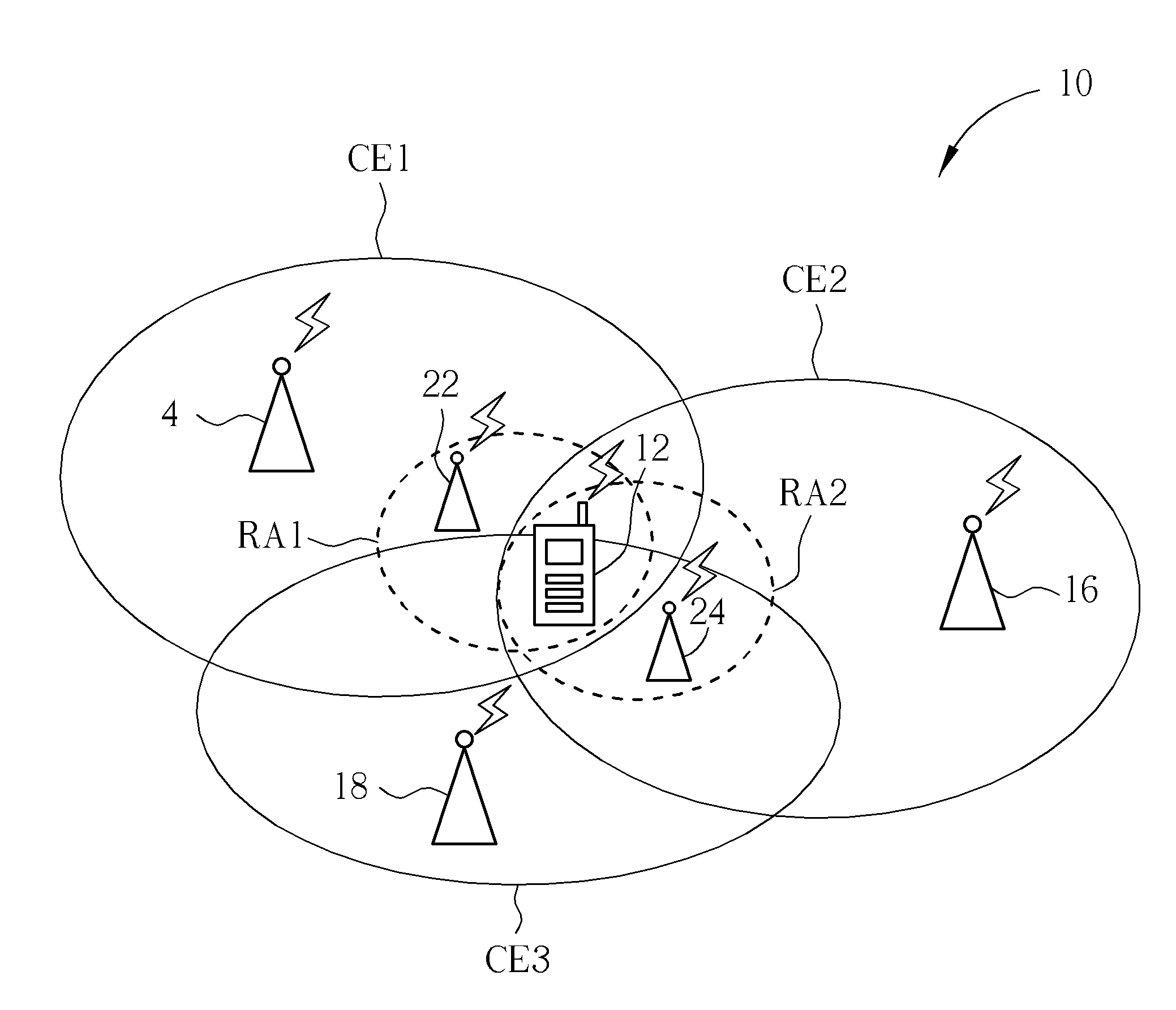
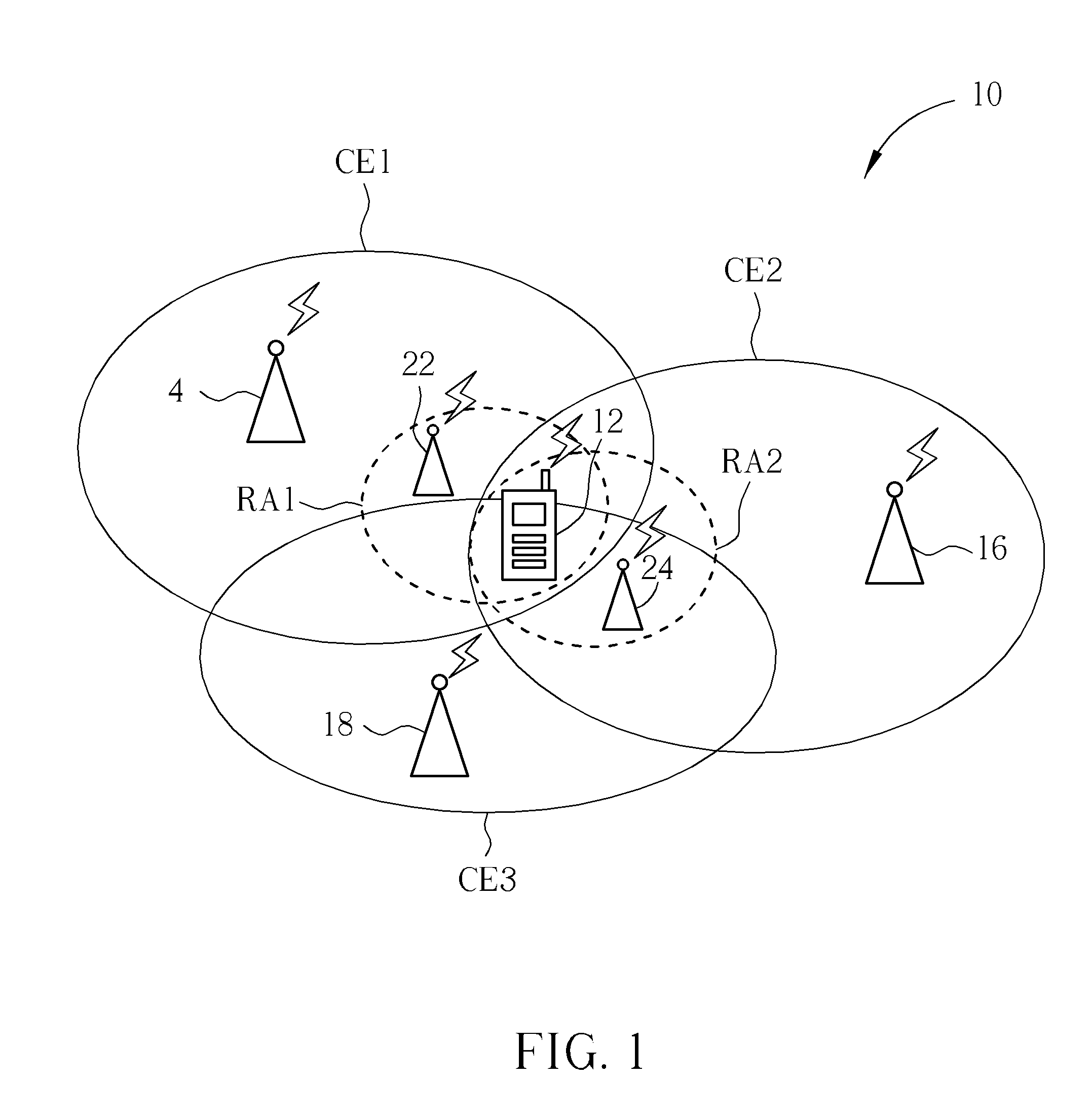
[0027]Please refer to FIG. 1, which is a schematic diagram of an examplary wireless communications system 10 (e.g. long term evolution-advanced (LTE-A) system) supporting relay deployment, coordinated multiple point (CoMP) transmission and simultaneous transmission / reception on multiple carriers (e.g. carrier aggregation). For convenience of explaining the concept of the disclosure, the wireless communications system 10 is illustrated to simply include a mobile device 12, and base stations 14-18 controlling cells CE1-CE3. The base stations 14, 16 are deployed with relays 22, 24 having coverages RA1, RA2, respectively. In the LTE-A system, the base stations 14-18 and the relays 22, 24 can be regarded as part of a network, i.e. E-UTRAN (evolved-UTRAN), comprising a plurality of eNBs (evolved Node-Bs) each controlling a cell, whereas the mobile device 12 is referred as to a user equipments (UE) that can be devices such as mobile phones, portable computer systems, etc. This terminology ...


PUM


Abstract

A method for enhancing power control mechanism for a mobile device in a wireless communications system includes enabling a repetition function by which the mobile device repeatedly transmits a feedback signal in a plurality of consecutive subframes, receiving downlink signaling indicating an uplink grant as well as a power control command and allocation of a subframe of an uplink transmission, and not performing the uplink transmission in the subframe when the subframe collides with one of the consecutive subframes.

Description

CROSS REFERENCE TO RELATED APPLICATIONS[0001]This application claims the benefit of U.S. Provisional Application No. 61 / 219,778, filed on Jun. 24, 2009 and entitled “Method and Apparatus for power control enhancement”, the contents of which are incorporated herein in their entirety.BACKGROUND OF THE INVENTION[0002]1. Field of the Invention[0003]The present invention relates to a method used in a wireless communications system and related communication device, and more particularly, to a method for enhancing power control mechanism in a wireless communications system and related communication device.[0004]2. Description of the Prior Art[0005]A long-term evolution (LTE) system, initiated by the third generation partnership project (3GPP), is now being regarded as a new radio interface and radio network architecture that provides a high data rate, low latency, packet optimization, and improved system capacity and coverage. In the LTE system, a radio access network known as an evolved u...

Claims


Application Information

Patent Timeline
Patent Type & Authority Applications(United States)
IPC IPC(8): H04W52/04
CPCH04B7/2606H04W52/146H04W52/34H04W72/042H04W84/047H04W52/545H04L1/1858H04L1/1887H04W72/23
Inventor JEN, YU-CHIH
Owner HTC CORP
Why Eureka
Try Eureka