Method and system for dynamically routing between a radio access network and distributed antenna system remote antenna units

a technology of distributed antenna system and radio access network, applied in the field of wireless communication, can solve the problems of increasing the number (and, accordingly, the density) of base stations, and reducing the number of calls to be dropped, and achieve the effect of convenient change of ran-das correlations

Active Publication Date: 2007-10-23
SPRINT SPECTRUM LLC
View PDF5 Cites 138 Cited by
  • Summary
  • Abstract
  • Description
  • Claims
  • Application Information

AI Technical Summary

Benefits of technology

[0008]The present invention provides an improved mechanism for routing communication traffic between a radio access network and DAS remote antenna units. In accordance with an exemplary embodiment of the invention, a DHU and each DAS remote antenna unit served by the DHU will sit as a respective node on at least one packet-switched network (e.g., IP network, ATM network, etc.) Further, the DHU will maintain a set of mapping data that correlates one or more coverage segments of a cellular radio access network with one or more DAS antenna unit addresses on the packet-switched network (e.g., DAS antenna unit IP addresses). Advantageously, an administrator of the DAS can then alter the mapping data whenever desired, to conveniently change the RAN-DAS correlations, so as to distribute RAN coverage in a desired manner among the DAS antenna units.

Problems solved by technology

Designing a cellular network for a high quality of service thus involves a number of issues.
However, a larger cell would encompass more subscribers and may cause calls to be dropped if the capacity of the BTS is exceeded.
On the other hand, increasing the number (and, accordingly, the density) of base stations can be costly, not to mention the regulatory and architectural challenge of finding (and leasing) a desirable location for each BTS and the task of arranging for backhaul communications from each new BTS to other network entities such as the BSC and MSC.

Method used


Image

  • Method and system for dynamically routing between a radio access network and distributed antenna system remote antenna units
  • Method and system for dynamically routing between a radio access network and distributed antenna system remote antenna units
  • Method and system for dynamically routing between a radio access network and distributed antenna system remote antenna units

Examples


Embodiment Construction

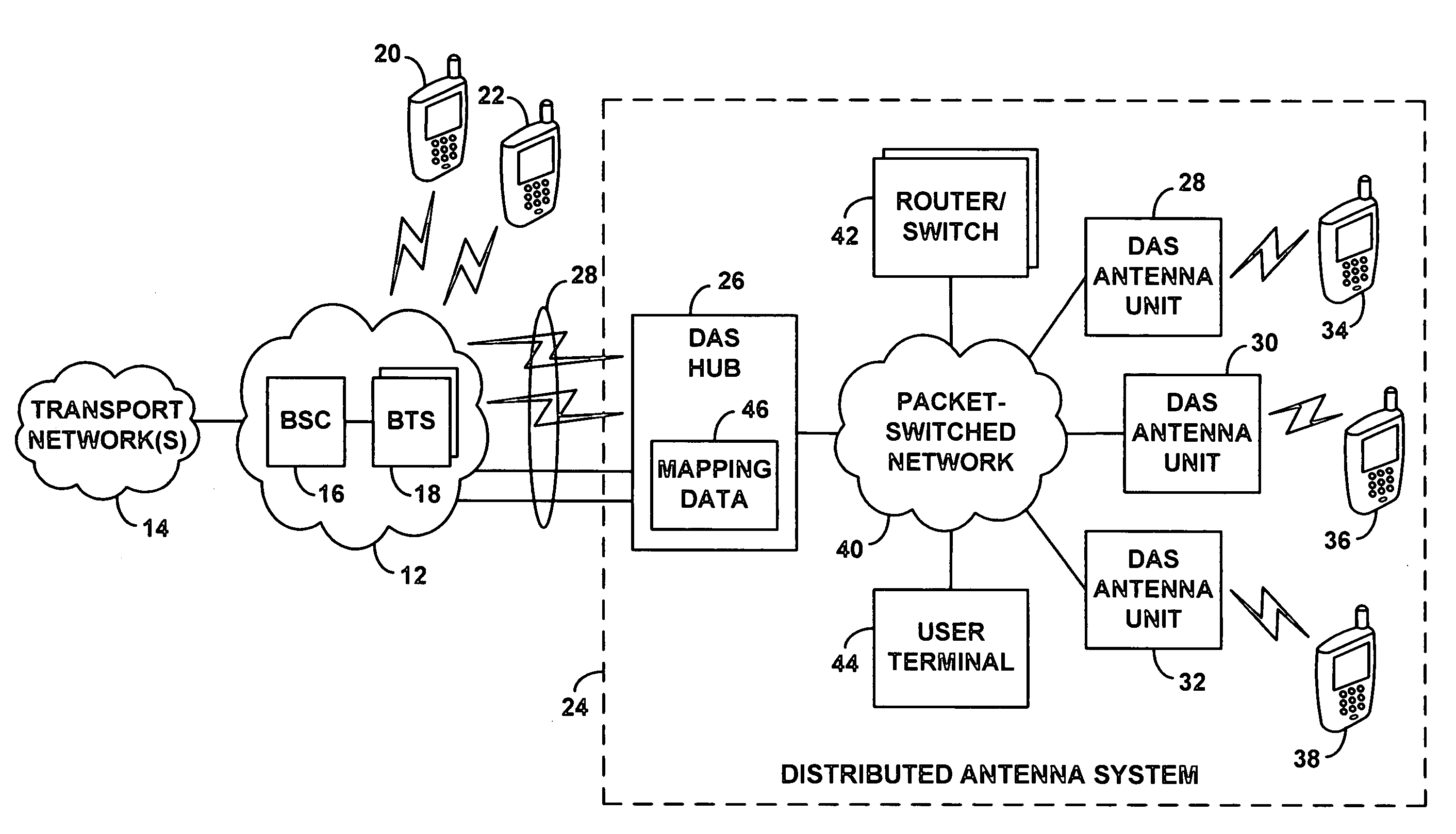
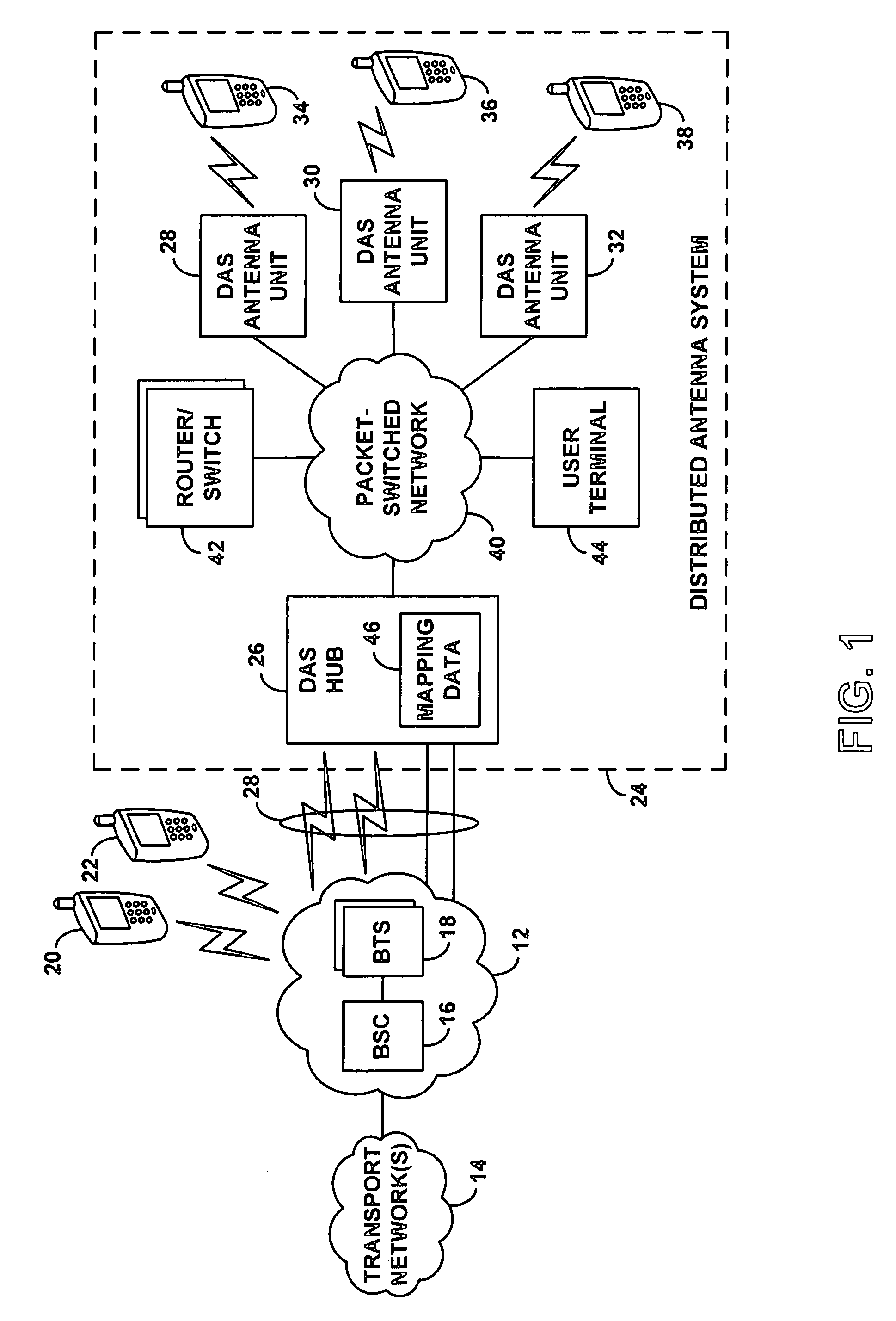
[0022]Referring to the drawings, FIG. 1 is a simplified block diagram of a system arranged in accordance with an exemplary embodiment of the invention. It should be understood, of course, that this and other arrangements and functions described herein are provided by way of example only and that numerous variations may be possible. For instance, elements can be added, omitted, combined, distributed, reordered, repositioned, or otherwise changed while remaining within the scope of the invention as defined by the claims. Further, it should be understood that various functions described herein can be carried out by hardware, firmware, and / or software (e.g., one or more processors programmed with machine language instructions to carry out the functions).

[0023]The system of FIG. 1 includes at its center a radio access network (RAN) 12, which functions in a generally known manner to engage in radio frequency (RF) communication with one or more client devices and to provide the client devi...


PUM


Abstract

An improved mechanism for routing communication traffic between a radio access network and distributed antenna system (DAS) remote antenna units. In accordance with an exemplary embodiment of the invention, a DAS hub and each DAS antenna unit served by the DAS hub will sit as a respective node on a packet-switched network. Further, the DAS hub will maintain or otherwise have access to a set of mapping data that correlates one or more radio access network coverage segments (e.g., cell sectors) with one or more DAS antenna unit addresses on the packet-switched network (e.g., IP addresses). Advantageously, an administrator of the DAS can then configure or alter the mapping data whenever desired, to conveniently set the RAN-DAS correlations and to thereby distribute RAN coverage in a desired manner throughout the DAS.

Description

FIELD OF THE INVENTION[0001]The present invention relates to wireless communications and more particularly to the arrangement and operation of distributed antenna systems.DESCRIPTION OF RELATED ART[0002]The art and popularity of wireless communications has grown significantly over recent years. Indeed, millions of people are engaging in voice and data communications using wireless communication devices such as cellular telephones and Personal Digital Assistants (PDAs). In principle, a user can communicate over the Internet or call anyone over the Public Switched Telephone Network (PSTN) from any place inside the coverage area of a cellular wireless network.[0003]In a typical cellular wireless network, an area is divided geographically into a number of cells and cell sectors, each defined by a radio frequency (RF) radiation pattern from a respective base transceiver station (BTS) antenna. The base station antennae in the cells are in turn coupled to a base station controller (BSC), w...

Claims


Application Information

Patent Timeline
Patent Type & Authority Patents(United States)
IPC IPC(8): H04Q7/20H04Q7/22H04W16/26H04W40/02H04W80/04H04W88/08
CPCH04W16/26H04W88/085H04W80/04H04W40/02
Inventor OH, DAE-SIKSILL, TIMOTHY W.
Owner SPRINT SPECTRUM LLC
Why Eureka
Try Eureka