Mouse structure

a mouse and structure technology, applied in the field of mouse structure, can solve the problems of increasing the overall volume of the mouse, increasing the power consumption of the mouse, and requiring frequent battery replacement, so as to improve the arrangement of the inner elements and improve the mouse structur

Inactive Publication Date: 2006-10-10
CHEN CLIFF
View PDF5 Cites 24 Cited by
  • Summary
  • Abstract
  • Description
  • Claims
  • Application Information

AI Technical Summary

Benefits of technology

[0010]An object of the present invention is to provide an improved mouse structure that improves the arrangement of inner elements for achieving a compact mouse.
[0011]It is another object of the invention to provide an improved mouse structure with an improved method of assembly that is fast and allows convenient battery changing, thus reducing production cost and assembly time.

Problems solved by technology

The wireless optical mouse utilizes light for sensing movement of the mouse, and the power consumption is consequently much more and thus this mouse requires frequent battery replacement.
1. The battery arrangement occupies a lot of space. When the battery is arranged on the bottom of the first kind mouse, the other elements must be disposed on the battery, and therefore the overall volume of the mouse must be increased. This results in inconvenience when carrying, and is contrary to the wireless and unrestricting trend.
2. The mouse has one more cover. This additional cover requires not only a lot of attention to engaging the cover on the battery chamber when replacing the battery, but also one more die for molding the cover. The whole cost and assembling time are increased.
3. The upper and lower shell (85, 86) of mouse are usually assembled by screwing or engaging with some hooks and grooves. This also consumes time when assembling the mouse.

Method used


Image

  • Mouse structure
  • Mouse structure
  • Mouse structure

Examples


Embodiment Construction

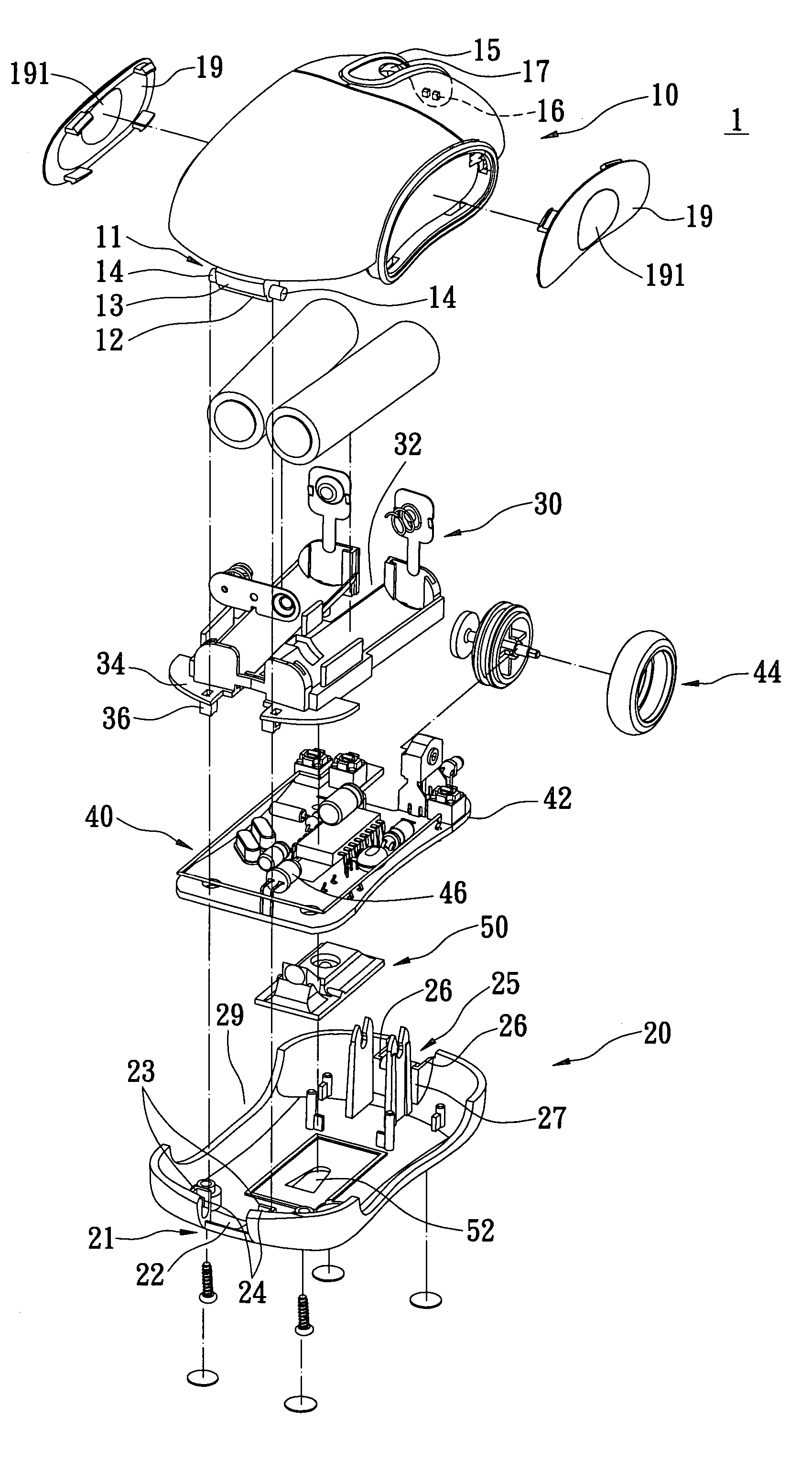
[0021]Referring to FIGS. 3 to 7, the present invention of an improved mouse structure 1 comprises a cover 10 and a base 20 pivotally assembled on the cover 10.

[0022]The cover 10 is an elliptically curved shell with two ends, comprising a pivoting portion 11 extending downwardly from one of the ends thereof, and a saddle 15 formed on a front portion thereof. The pivoting portion 11 has an extending portion 12 extending downwardly from an edge of the cover 10, and a pair of pivoting shafts 14 respectively protruding outwardly from two ends of the extending portion 12. The saddle 15 has a wheel hole 17 formed thereon for containing and projecting a wheel 44. The saddle 15 extends forwardly and downwardly for a predetermined length with a distal end and a hook 16 protrudes from an inner surface of the distal end of the saddle 15.

[0023]The base 20 comprises a receiving portion 21 formed on an end thereof for receiving the pivoting portion 11, an engaging seat 25 formed on another end the...


PUM


Abstract

An improved mouse structure has a cover and a base pivotally connected to the cover. The cover is an elliptically curved shell with two ends, and has a pivoting portion extending downwardly from one of the ends thereof as well as a hook formed on another end thereof. The base comprises a receiving portion formed on an end thereof for receiving the pivoting portion, an engaging seat formed on another end thereof, and an engaging hole formed in the engaging seat for engaging with the hook.

Description

BACKGROUND OF THE INVENTION[0001]1. Field of the Invention[0002]The present invention relates to an improved mouse structure, and particularly to a compact wireless optical mouse with improved arrangement of the inner elements for convenient carrying.[0003]2. Description of the Prior Art[0004]With the Windows operating system, the mouse has become an essential and indispensable computer peripheral. The mouse can be classified according to its function into two types, the optical mouse and mechanism mouse, and each type is further dividable into the wired and wireless mouse. The wireless optical mouse utilizes light for sensing movement of the mouse, and the power consumption is consequently much more and thus this mouse requires frequent battery replacement. Referring to FIG. 1, the prior art battery device can be classified as two kinds. In the first kind, the mouse 80 is formed with a battery chamber 82 on a bottom thereof, and a detachable cover 84 covers the battery chamber 82. ...

Claims


Application Information

Patent Timeline
Patent Type & Authority Patents(United States)
IPC IPC(8): G09G5/08G06F3/0354
CPCG06F3/03543
Inventor CHEN, CLIFF
Owner CHEN CLIFF
Why Eureka
Try Eureka