
Antenna arrangement for an electronic device and an electronic device including same

Inactive Publication Date: 2007-05-08
TIMEX GROUP
View PDF20 Cites 137 Cited by
  • Summary
  • Abstract
  • Description
  • Claims
  • Application Information

AI Technical Summary

Benefits of technology

[0006]Therefore, it is generally an object and advantage of the present invention to provide an improved antenna arrangement for a device comprising a metal casing.
[0007]It is still a further object and advantage of the present invention to provide an improved antenna arrangement for a wristworn device having improved signal transmission and reception functionality.
[0008]It is another object and advantage of the present invention to provide an improved antenna arrangement for a wristworn timepiece that incorporates therein a receiver, transmitter and / or transceiver.
[0009]It is yet another object of the present invention is to provide an improved antenna arrangement for a wristworn device that reduces the number of components of the device yet provides satisfactory or even improved signal reception and / or transmission.
[0010]Yet another object and advantage of the present invention is to provide an improved antenna arrangement that reduces ESD.

Problems solved by technology

While these arrangements may have been satisfactory for their intended uses, they all are perceived to be deficient in various respects.
However, use of a loop antenna in a metal case, such as a watch casing, has been found to have drawbacks and to be less than optimal, typically because of the poor performance due to the shielding of the antenna by the metal case itself.
Additionally, electro-static discharge (ESD) is also a known problem when using a metal casing.
However, this known example utilizes a coil antenna with a ferrite core, which doesn't provide a desirable distance communication range.
Moreover, the use of coil antennas in such devices are limited to short range (e.g. 1–2 feet) communications, which are less than desirable in the communications contemplated by the present invention.
With all of the known obstacles related to shielding and performance of a loop antennas in a metal casing, it is believed that the prior art designs have been less than effective in incorporating a loop antenna into a device having a metal casing.

Method used


Image

  • Antenna arrangement for an electronic device and an electronic device including same
  • Antenna arrangement for an electronic device and an electronic device including same

Examples


first embodiment

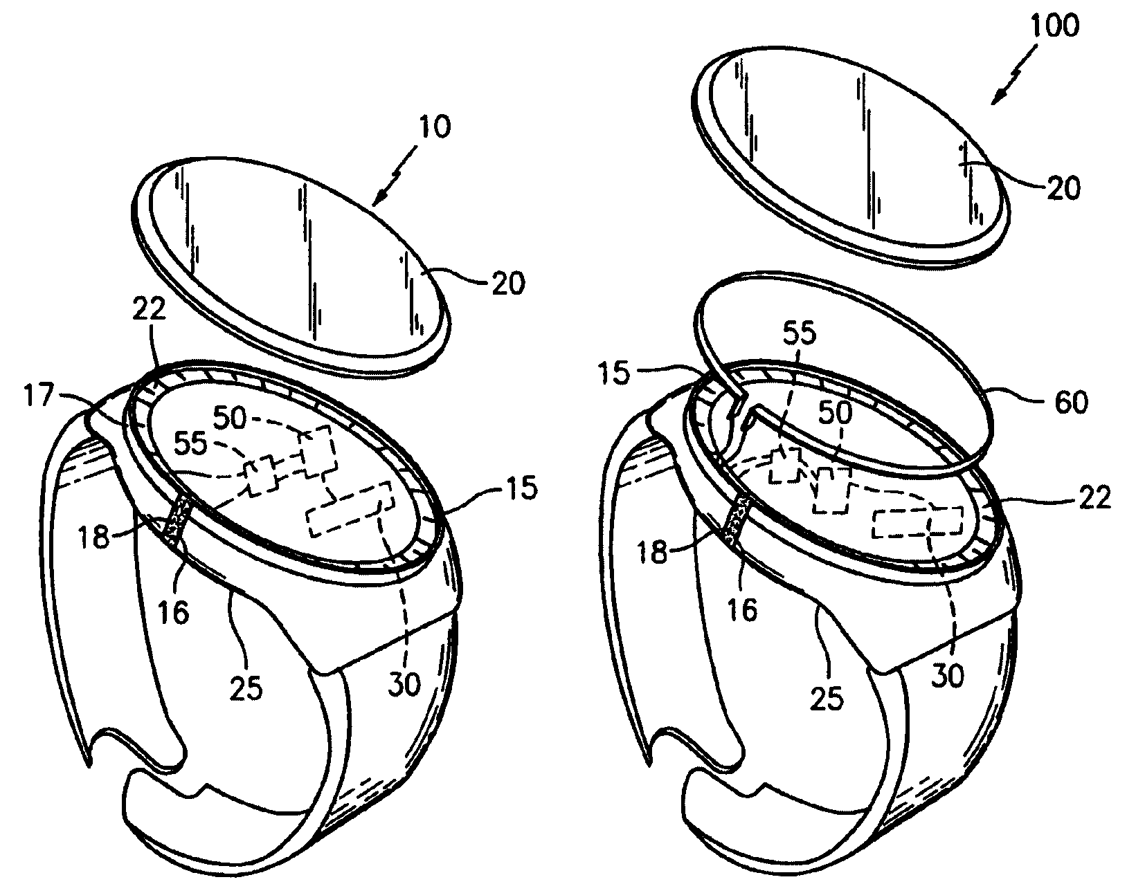
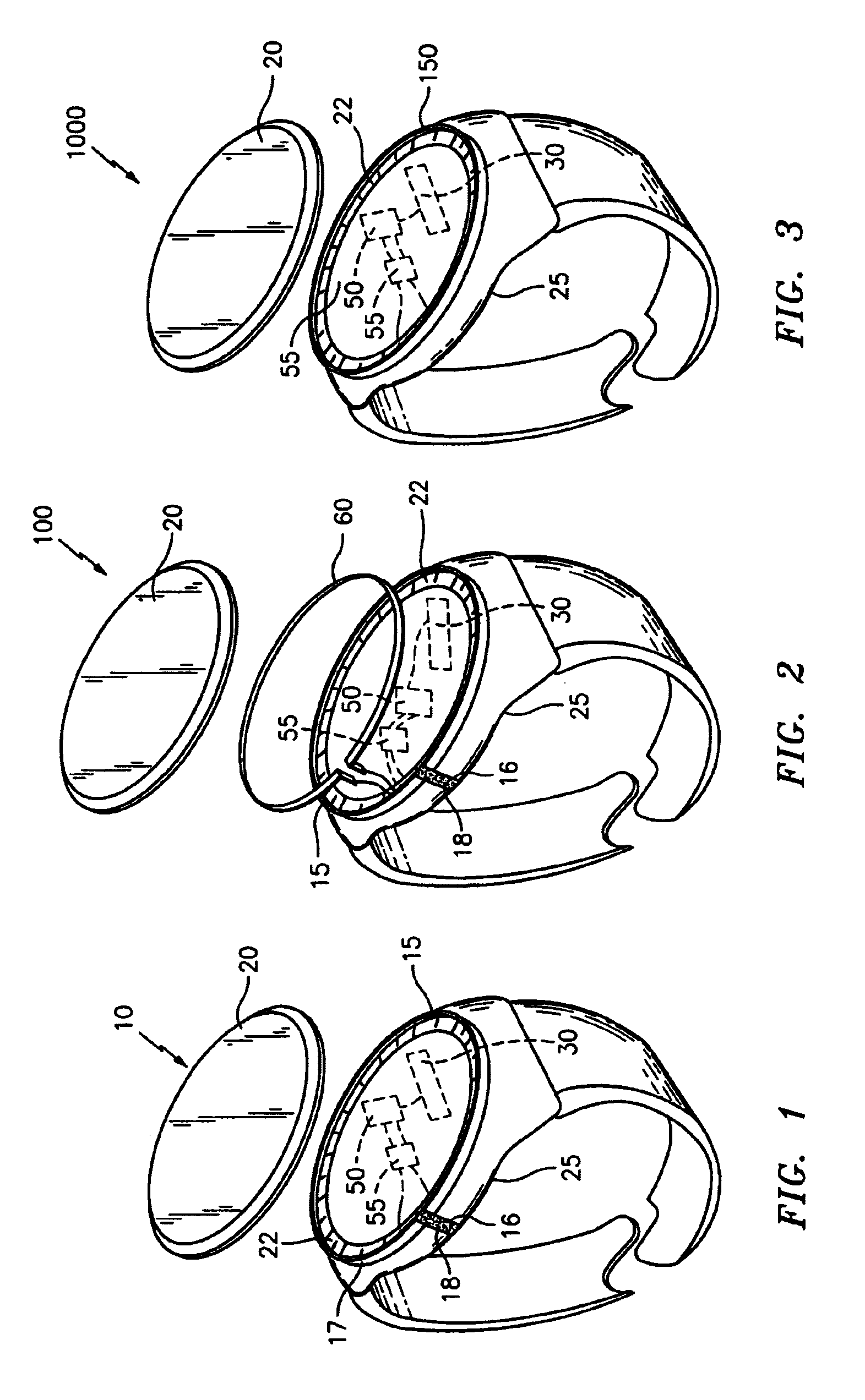
[0022]Reference shall be first made FIG. 1 and the following disclosure, which depicts and discloses a wristworn device, generally indicated at 10, constructed in accordance with the present invention.

[0023]In a preferred embodiment, device 10 is a wristworn device, and preferably a timepiece. However, as indicated above, device 10 need not be limited to a timepiece or wristwatch, and may be a variety of other devices, such as a heart rate monitor, glucose monitor or other communication device, examples of which are disclosed in Published Application Serial No. 2004 / 0233788 (the '788 Published Application), which is hereby incorporated by reference in its entirety.

[0024]As illustrated in FIG. 1, device 10 preferably comprises a metal watchcase 15, a glass or plastic transparent watch crystal 20 that allows viewing of a watch dial 22, a case back 25 and a watch movement generally indicated at 30 that contains the electrical and mechanical mechanisms for timekeeping, including hand mo...

second embodiment

[0032]Reference is now made to FIG. 2 in connection with the following disclosure, which depicts and discloses a wristworn device, generally indicated at 100, constructed in accordance with the present invention.

[0033]In this preferred embodiment, device 100 is likewise preferably a wristworn device, and preferably a timepiece. However, as indicated above with respect to device 10, device 100 need not be limited to a timepiece or wristwatch, and may be a variety of other devices, such as those disclosed above.

[0034]Similar to device 10, device 100 also preferably comprises metal watchcase 15, glass or plastic transparent watch crystal 20, case back 25, a dial 22, a controller means / watch movement 30 such as that disclosed above, and radio communication device 50 that is coupled to the controller means. Again, the controller means may comprise a controller such as that disclosed in the aforementioned '788 Published Application, the subject matter of which is incorporated herein by re...

third embodiment

[0040]Reference is now made to FIG. 3 in connection with the following disclosure, which depicts and discloses a wristworn device, generally indicated at 1000, constructed in accordance with yet the present invention.

[0041]In this preferred embodiment, device 1000 is likewise preferably a wristworn device, and preferably a timepiece. However, as indicated above with respect to device 10 and 100, device 1000 need not be limited to a timepiece or wristwatch, and may be a variety of other devices, such as those disclosed above and in the '788 Published Application.

[0042]Similar to devices 10 and 100, device 1000 also preferably comprises a metal watchcase, glass or plastic transparent watch crystal 20, a dial 22, a case back 25, controller means / watch movement 30 such as that disclosed above, and radio communication device 50 coupled to controller means 30. The design and construction of the foregoing features are similarly constructed.

[0043]This third embodiment most significantly dif...


PUM


Abstract

A wristworn device comprising a radio communication device for receiving from and / or transmitting signals to a radio communication device external to the wristworn device. In at least one embodiment, the casing comprises a metallic watchcase having a slot, and wherein the watchcase is electrically coupled to the radio communication device to function as the antenna. In another embodiment, a metallic loop is provided in the casing proximate the watchcase, wherein the metallic loop is electrically coupled to the radio communication device to function as the antenna and the watchcase comprises a slot and functions as an element for the reception and / or transmission of electromagnetic radiation. In a third embodiment, the metallic watchcase does not have a slot and the watchcase is electrically coupled to the radio communication device to function as the antenna.

Description

BACKGROUND OF THE INVENTION[0001]The present invention relates generally to antennas, and in particular, to an improved antenna for a wristworn device having signal transmitting and / or receiving capabilities. In exemplary embodiments, the wristworn device is a timepiece such as a wristwatch, but, as will become quite clear below, a timepiece or wristwatch is only by way of example and not limitation. In particular, the invention is primarily directed to improved signal transmission and reception within a metal casing, such as a casing for a timepiece.[0002]The prior art is full of examples of antennas associated with wristworn devices, such as wristwatches. As would be well known to those skilled in the art, loop antennas are particularly advantageous due to their size and directivity, as it is well known that a loop antenna is desirable since it has a geometry that essentially “pulls in” signals from 360 degrees (i.e. from all different azimuths and orientations). For example, U.S....

Claims


Application Information

Patent Timeline
IPC IPC(8): G04B47/00G04C11/02H01Q1/12G04G21/04
CPCG04G21/04H01Q1/273H04B1/385G04R60/02G04R60/06
Inventor DEROSA, RONALD J.
Owner TIMEX GROUP
Learn More