Arrangement for Detecting a Position of a Plunger

Active Publication Date: 2018-05-31
SANOFI AVENTIS DEUTSCHLAND GMBH
View PDF6 Cites 0 Cited by
  • Summary
  • Abstract
  • Description
  • Claims
  • Application Information

AI Technical Summary

Benefits of technology

[0009]It is an object of the present invention to provide an improved arrangeme

Problems solved by technology

Administering an injection is a process which presents a number of risks and challenges for users and healthcare professionals, both mental and physical.
There are numerous disadvantages to the user from this approach.
This means that the user can deliver an underdose if the device is not used properly (i.e. the plunger is not fully pressed to its end position).
Injection forces ma

Method used


Image

  • Arrangement for Detecting a Position of a Plunger
  • Arrangement for Detecting a Position of a Plunger
  • Arrangement for Detecting a Position of a Plunger

Examples


Example

[0037]Corresponding parts are marked with the same reference symbols in all figures.

DETAILED DESCRIPTION OF PREFERRED EMBODIMENTS

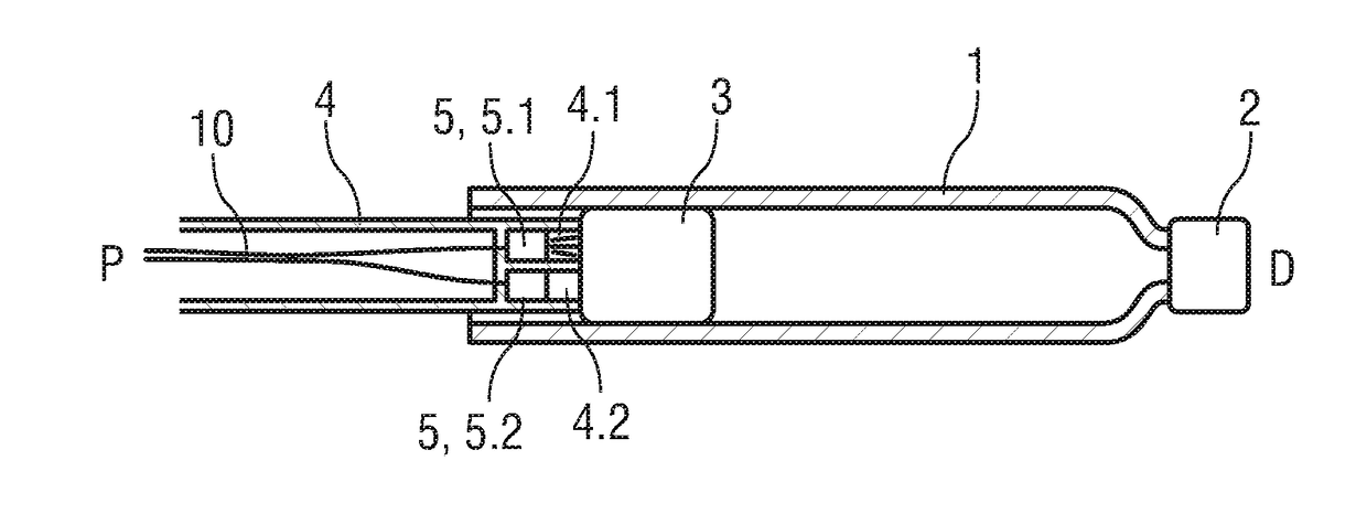
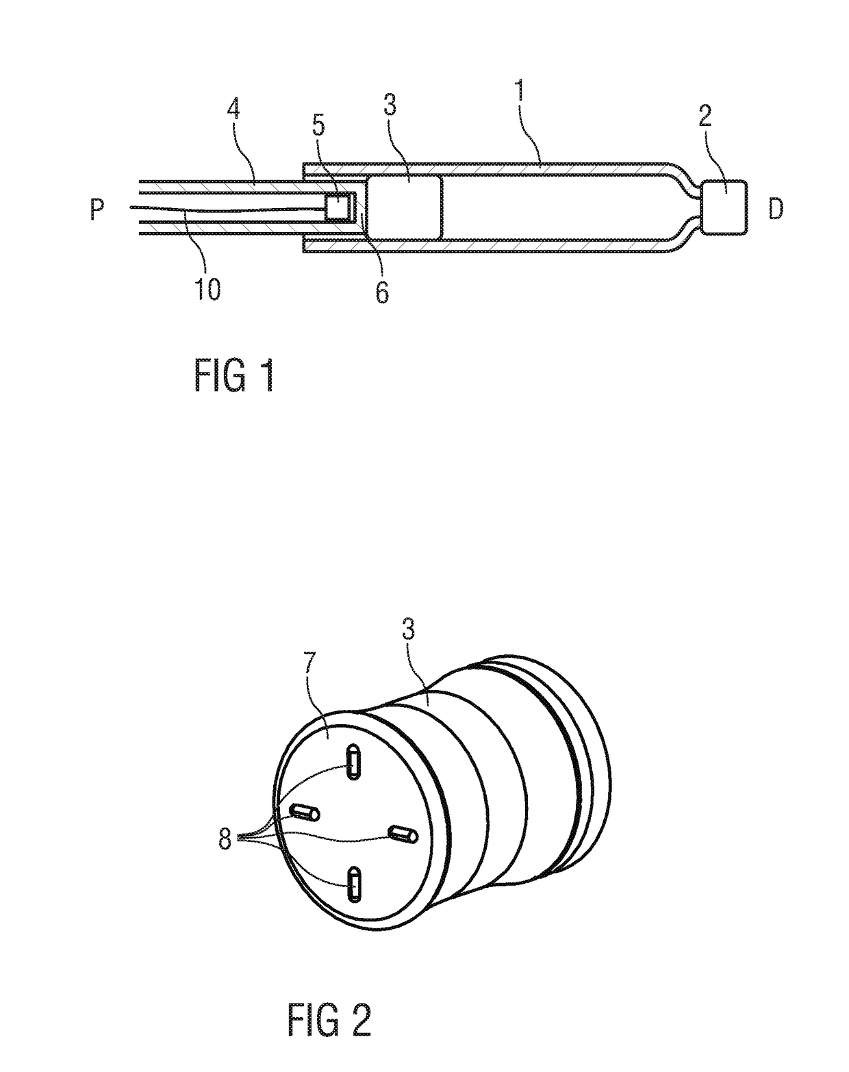
[0038]FIG. 1 is a schematic longitudinal detail section of an exemplary embodiment of a drug cartridge 1 or syringe with a septum 2 or discharge nozzle at a distal end and a bung 3 or stopper disposed within the cartridge 1 near a proximal end. A plunger 4 is arranged for displacing the bung 3 within the cartridge 1 for dispensing the drug contained within the cartridge 1.

[0039]A proximity sensor 5 arranged as an imaging sensor is disposed within the plunger 4. The proximity sensor 5 can be of any type suitable for imaging, but preferentially may be of the type comprising a light source, light sensor, lens and processing unit. The proximity sensor 5 is located close to a flat transparent distal end 6 of the plunger 4 facing the bung 3 and aligned to image the bung 3.

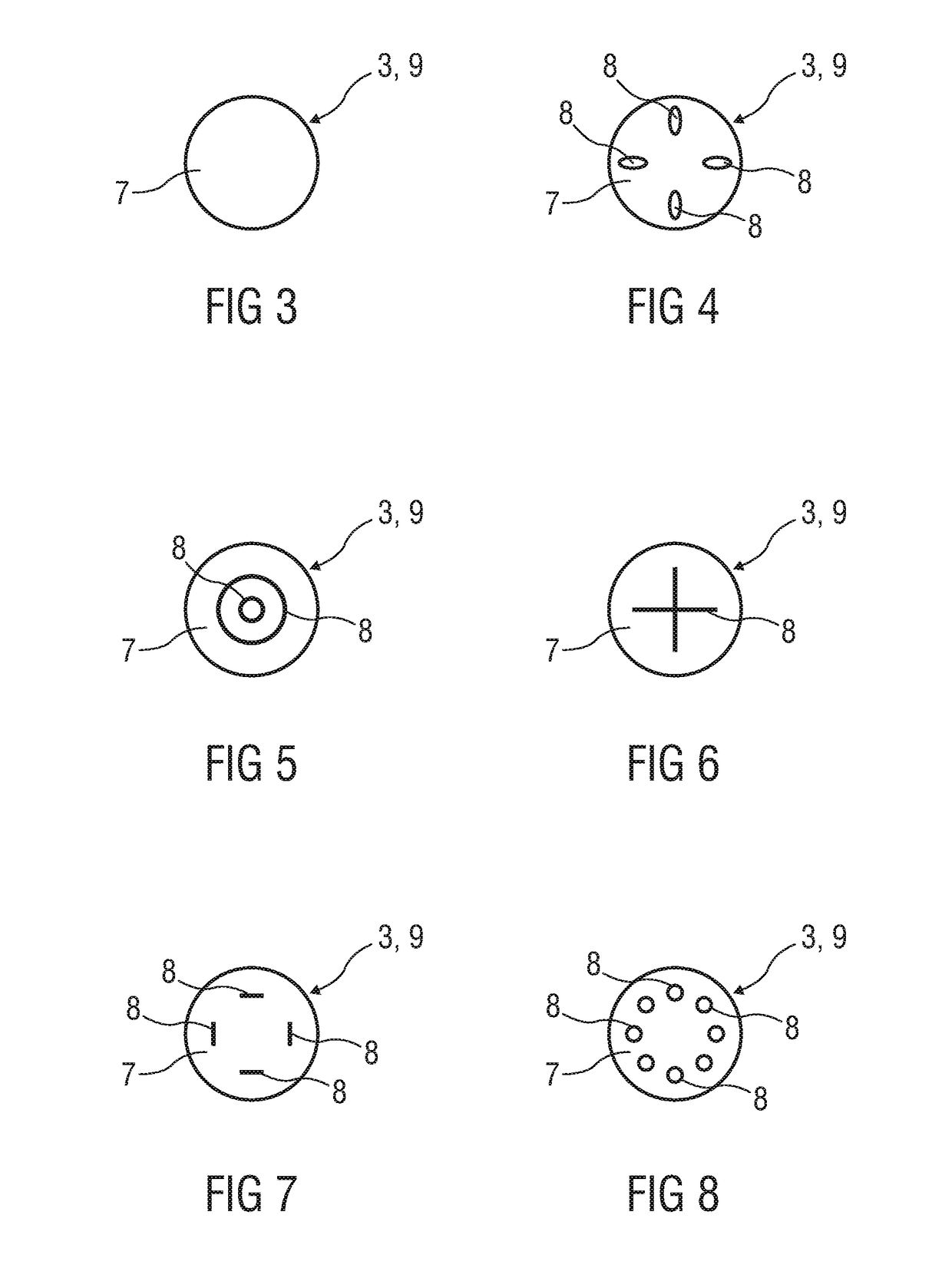
[0040]FIG. 2 is a schematic perspective view of an exemplary embodiment of the bung 3. In t...


PUM


Abstract

The invention relates to an arrangement for detecting a position of a plunger (4) relative to a bung (3) in a drug cartridge (1), comprising a proximity sensor (5) located close to a distal end (6) of the plunger (4) facing the bung (3) and aligned to receive light reflected by the bung (3).

Description

TECHNICAL FIELD[0001]The invention relates to an arrangement for detecting a position of a plunger relative to a bung in a drug cartridge.BACKGROUND OF THE INVENTION[0002]Administering an injection is a process which presents a number of risks and challenges for users and healthcare professionals, both mental and physical.[0003]Injection devices (i.e. devices capable of delivering medicaments from a medication container) typically fall into two categories—manual devices and auto-injectors.[0004]In a manual device—the user must provide the mechanical energy to drive the fluid through the needle. This is typically done by some form of button / plunger that has to be continuously pressed by the user during the injection. There are numerous disadvantages to the user from this approach. If the user stops pressing the button / plunger then the injection will also stop. This means that the user can deliver an underdose if the device is not used properly (i.e. the plunger is not fully pressed t...

Claims


Application Information

Patent Timeline
IPC IPC(8): A61M5/20G01D5/34A61M5/145A61M5/31G01D5/32G01S17/08
CPCG01D5/34A61M5/20A61M5/1452A61M5/3146G01D5/32A61M2205/587G01S17/08A61M5/31515A61M2005/206A61M2205/3306
Inventor DRAPER, PAUL RICHARDMORRIS, ANTHONY PAULGILMORE, STEPHEN FRANCIS
Owner SANOFI AVENTIS DEUTSCHLAND GMBH
Why Eureka
Try Eureka