Crash helmet with thermoelectric cooling

a technology of thermoelectric modules and helmets, applied in the field of crash helmets, can solve the problems of visor fogging, uncomfortable or even unsafe wearing conditions, and obscure vision, and achieve the effects of improving interior cooling efficiency, improving thermal module arrangement, and improving air flow

Inactive Publication Date: 2007-11-20
R & G MACHINE TOOL
View PDF23 Cites 138 Cited by
  • Summary
  • Abstract
  • Description
  • Claims
  • Application Information

AI Technical Summary

Benefits of technology

[0009]A further object of the invention is to provide such a helmet cooling system having improved air flow and having an improved thermoelectric module arrangement which provides more efficient interior cooling than was previously available.

Problems solved by technology

Since the wearer's head emits heat, this can cause discomfort or even unsafe wearing conditions.
For example, heat which is trapped within the helmet interior can cause the visor to fog and obscure vision.
Sweat dripping down in the wearer's face can also be distracting and obstruct the vision of the wearer.
Even if a movable closure plate is present, closing the intake vent causes the interior to steam up and create a stuffy, hot feeling.
However, these alternative designs suffered from various shortcomings such as poor interior circulation, allowing rain and water to seep in.
Certain of the designs were complicated to implement, requiring the assembly of many parts.
Also, the thermoelectric cooling component design was not of an optimum design to provide the optimum cooling effect for the helmet interior.

Method used


Image

  • Crash helmet with thermoelectric cooling
  • Crash helmet with thermoelectric cooling
  • Crash helmet with thermoelectric cooling

Examples


Embodiment Construction

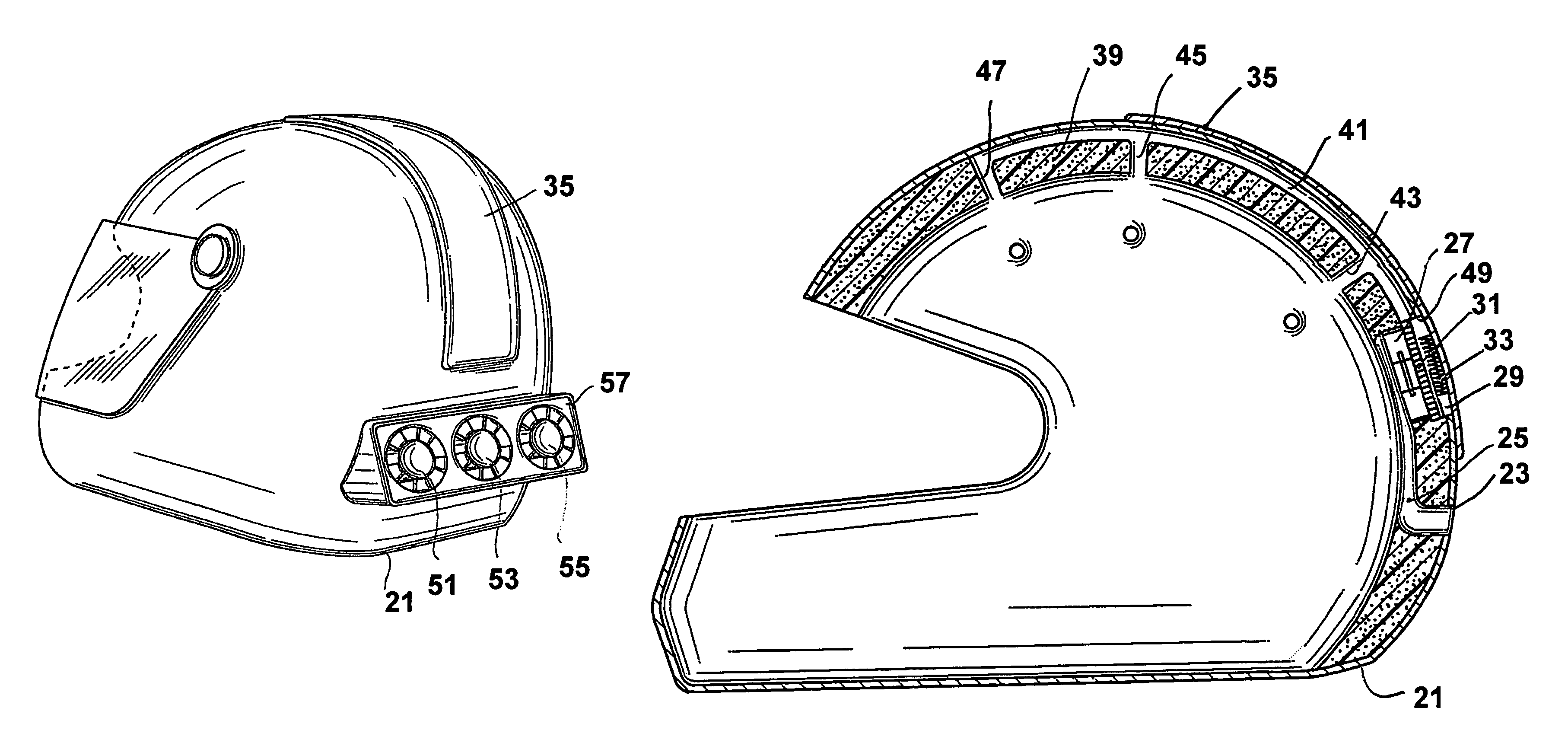
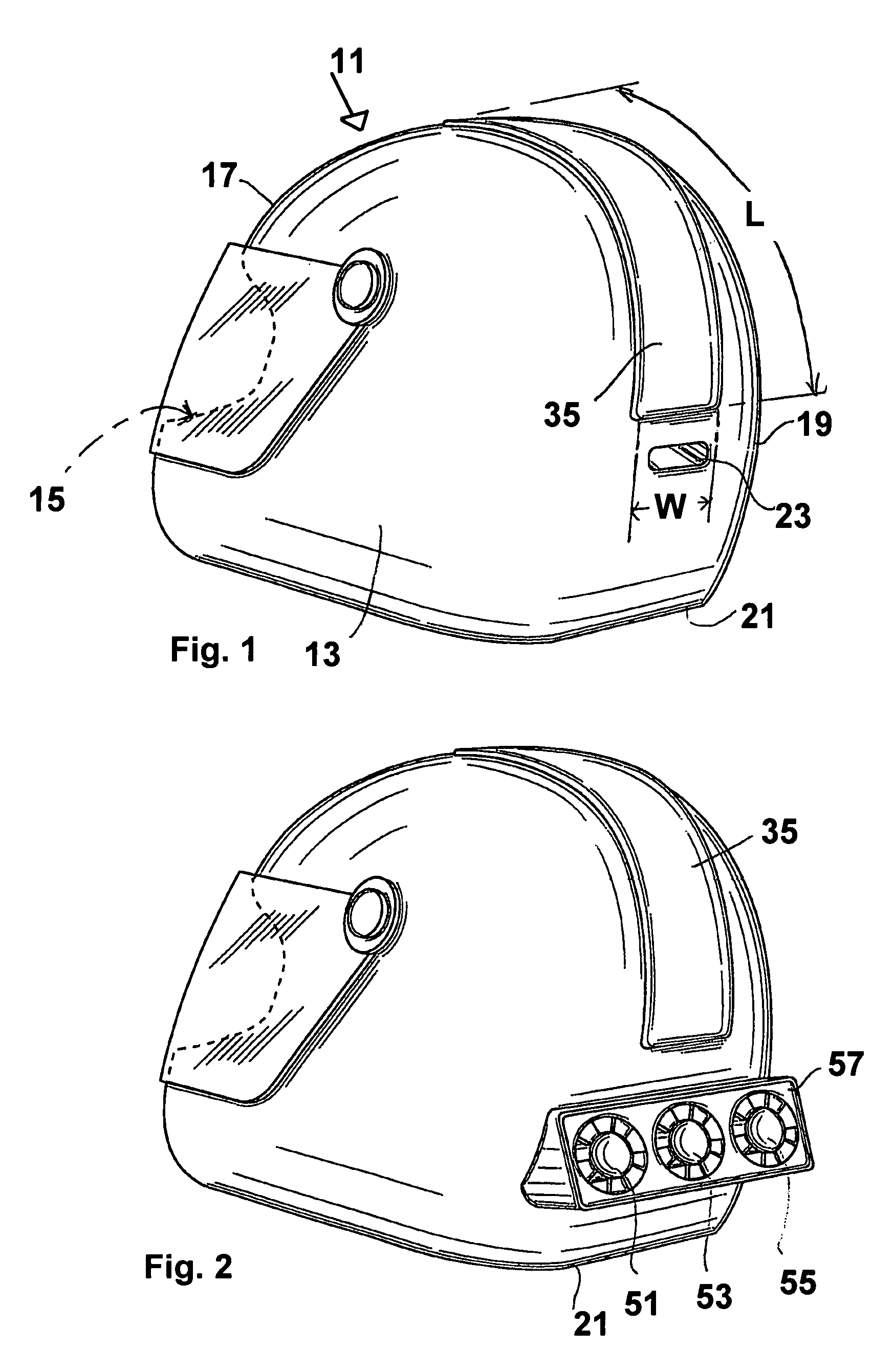
[0020]Turning to FIG. 1, there is shown an air conditioned crash helmet 11 of the invention. The helmet 11 is formed from an impact resistant body having an exterior 13, an interior 15 which defines a head receiving cavity, a front region 17 and having a back region 19 which is located adjacent a lower edge 21 of the helmet body. The helmet body can be formed of any convenient material, typically a synthetic plastic or acrylic plastic. One advantage of the present invention is that a stock crash helmet, such as a motorcycle helmet, can be fitted with the air conditioning system of the invention.

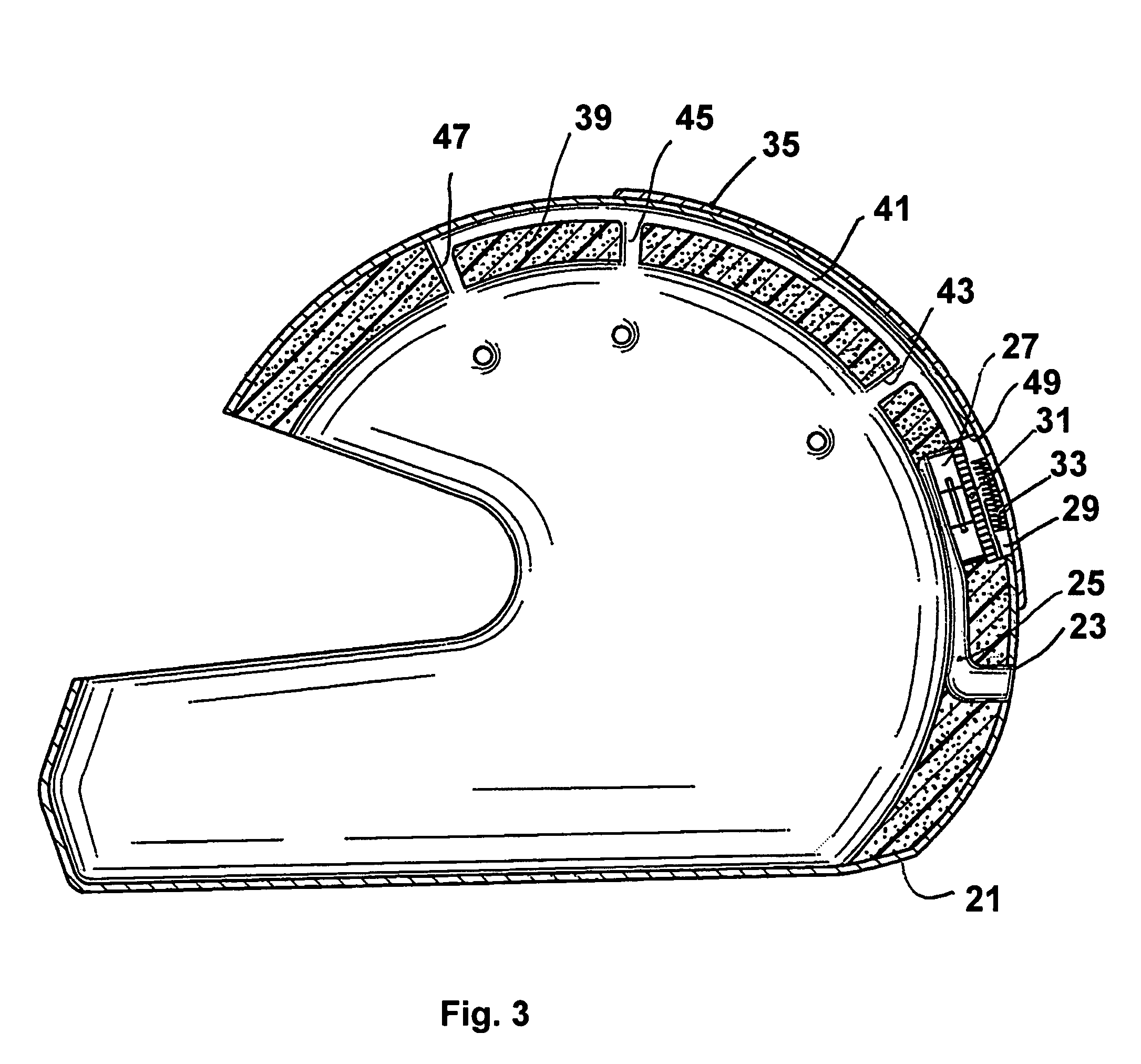
[0021]As best seen in FIG. 3, a first opening 23 is formed in the helmet body located at the back region 19 thereof adjacent the lower edge 21. The first opening 23 defines an air intake passage 25 for the intake of external air.

[0022]In the embodiment of the invention shown in FIG. 3, at least one blower fan 27 communicates with the air intake passage 25 for drawing air into the intake passa...


PUM


Abstract

An conditioning system is shown for a helmet having an impact resistant body with an exterior, an interior which defines a head receiving cavity, a front region and having a back region which is located adjacent a lower edge of the helmet body. A first opening is provided in the helmet body located at the back region of the helmet body adjacent a lower edge thereof which acts as an air intake opening. A blower fan communicates with the air intake passage for drawing air into the intake passage and forcing the air from the back region of the helmet in the direction of the front region thereof. A thermoelectric cooling element is located in the helmet interior in communication with the intake passage downstream of the blower fan. The thermoelectric cooling element has a cold side and a hot side. A DC power source is provided for powering the thermoelectric cooling element. An external heat sink is located on the helmet exterior and is connected to the hot side of the thermoelectric cooling element by means of a second opening in the helmet body. Air passing over the thermoelectric cooling element is cooled and air conditions the head receiving region of the helmet.

Description

BACKGROUND OF THE INVENTION[0001]1. Field of the Invention[0002]The present invention relates generally to crash helmets such as motorcycle helmets and, more specifically, to such a helmet having a built in air conditioning module which provides cooling and temperature control for the inside of the helmet.[0003]2. Description of the Prior Art[0004]A variety of “crash” type helmets are known in the prior art for use in a variety of different industries or avocations. Generally speaking, the helmet is used to protect the head of the wearer by preventing major impacts, thereby serving to safeguard the well being of the wearer. For example, such helmets are commonly used by motorcycle enthusiasts and stock car and race car drivers. For purposes of the present discussion, a motorcycle embodiment of the invention will be described. However, it will be understood that other type crash helmets can also benefit from the improved design of the invention.[0005]While various styles of helmets a...

Claims


Application Information

Patent Timeline
Patent Type & Authority Patents(United States)
IPC IPC(8): A42C5/04
CPCA42B3/285
Inventor GOLDSBOROUGH, RICHARD
Owner R & G MACHINE TOOL
Why Eureka
Try Eureka