Liquid crystal display device

a display device and liquid crystal technology, applied in non-linear optics, instruments, optics, etc., can solve the problems of thinness and lightness in weight, decrease in contrast ratio, and inferior display performance of liquid crystal display itself, and achieve low power consumption and wide viewing angle.

Inactive Publication Date: 2007-07-17
PANASONIC LIQUID CRYSTAL DISPLAY CO LTD +1
View PDF27 Cites 131 Cited by
  • Summary
  • Abstract
  • Description
  • Claims
  • Application Information

AI Technical Summary

Benefits of technology

[0017]One of the objects of the present invention is to provide a liquid crystal display device which is capable of producing a display with a wide viewing angle and with a low power consumption.
[0018]Another one of the objects of the present invention is to provide a liquid crystal display device having a high brightness with a high polarizing conversion efficiency by specifying an optimum axial arrangement of a light control element and a polarizer, when the light control element is utilized for improving brightness at a normal angle.
[0019]Still another one of the objects of the present invention is to provide a liquid crystal display device which is capable of realizing improvement of the efficiency of light utilization and the brightness at a normal angle by using a waveguide, which is capable of maintaining polarization of light reflected from a reflective polarizer and of improving the directivity.

Problems solved by technology

However, the liquid crystal display itself is still inferior to a CRT in display performance, such as a moving image display, viewing angle, and color reproduction.
However, both of the TN and STN modes have a narrow viewing angle, and other problems, such as image reversal in a grayscale display and a multicolor display, and a decrease in contrast ratio.
On the other hand, demands for the liquid crystal display device of note-type personal computer are not only thinness and lightness in weight, but also low power consumption and high brightness in the display.
The display has a problem in that the power consumption of the back light has been significantly increased for obtaining a brighter display, because the transmission factor of the screen is low, in addition to the complexity in the collimating structure and the screen structure.
It has been understood that an increase in the input power to the lamps has an undesirable effect on the display, such as an increase in the temperature due to heating (for instance, providing an inferior image quality and a shortening of the life of the lamp), in addition to an increase in the power consumption.
However, in the above-mentioned device, the efficiency of the polarizing conversion has not been considered, especially when these light control elements are used for improving the brightness at a normal angle.
Furthermore, the efficiency of the polarizing conversion has not been considered when the light control elements are used.
Accordingly, when its optical axis is shifted from the incident angle of incident linearly polarized light, the polarization is changed, and, as the result, a decrease in the efficiency of the polarizing conversion results.
Furthermore, it was found that the efficiency of the polarizing conversion was decreased if two light control elements were arranged so as to intersect at right angles.
However, any problems concerning oblique incident light relating to the characteristics of the light source have not been considered.
However, the cholesteric liquid crystal layer used as the color selective layer 512 has an undesirable degree of polarization to the oblique incident light, and, moreover, unnecessary light leakage of color is generated.
That means that with respect to the oblique incident light, a polarization other than a desired polarization is generated, leakage of light via a color other than a desired color is generated, and so a deterioration in display quality represented by decreases in contrast ratio, color reproduction and viewing angle characteristics results.
Furthermore, any uses of the polarized light effectively have not been considered at all.

Method used


Image

  • Liquid crystal display device
  • Liquid crystal display device
  • Liquid crystal display device

Examples


first embodiment

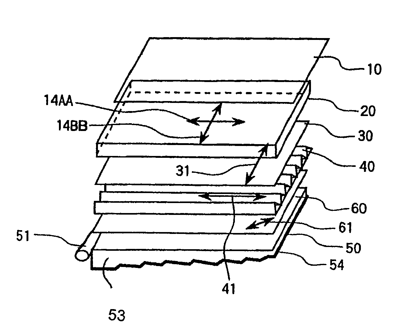
[0121]the present invention will be explained with reference to FIG. 1.

[0122]The present embodiment comprises an illumination device 50 providing particularly collimated light arranged in a lateral direction of the figure, the reflective polarizer 31 indicated in FIG. 10 comprising a dielectric multilayered film as the reflective polarizing selective means 30, the liquid crystal display element 20, the light control element 40, the birefringent medium 60, and the screen 10 having a wide viewing angle.

[0123]As the illumination device 50 which is used in the present embodiment, any edge light type back light or direct-below type back light can be used. The illumination device 50 relating to the present embodiment is composed in a manner that, for instance, definite fine grooves in a perpendicular direction to the figure are provided at the rear plane of the waveguide 53, as indicated in FIG. 1, and metal (aluminum, silver, and the like) having a high reflective index is used for the r...


PUM

PropertyMeasurementUnit
wavelengthaaaaaaaaaa
incident angleaaaaaaaaaa

Abstract

A liquid crystal display device includes an illumination device, a light control element arranged at a projected light side of the illumination device, a reflective polarizer arranged at an upper portion of the light control element so that the transmission axis of polarized light is adjusted, a liquid crystal display element for controlling polarization of projected light projected from the reflective polarizer, and a screen arranged at an upper portion of the liquid crystal display element. The light control element includes an isotropic medium without birefringence.

Description

CROSS REFERENCE TO RELATED APPLICATIONS[0001]This application is a continuation application of U.S. application Ser. No. 09 / 270,780, filed Mar. 17, 1999, now U.S. Pat. No. 7,006,173, the contents of which are incorporated herein by reference.BACKGROUND OF THE INVENTION[0002]The present invention relates to a liquid crystal display device, and, more particularly, to a liquid crystal display device having a viewing angle which is widened and a light utilization efficiency which is improved by re-utilization of light using polarizing conversion and polarizing wave length selectivity.[0003]Currently, the technical advancement in liquid crystal display devices, particularly in color liquid crystal display devices, is significant, such that display devices having almost the same image quality as a CRT have been realized. The liquid crystal display device has experienced an enlarged commercial market based on such features as thinness, lightness in weight, and low power consumption. Howeve...

Claims


Application Information

Patent Timeline
Patent Type & Authority Patents(United States)
IPC IPC(8): G02F1/1335G02F1/13357G02F1/1347
CPCG02F1/133536G02F1/133615G02F2001/133531G02F2001/133543G02F1/133543G02F1/133531G02F1/1335
Inventor HIYAMA, IKUOTSUMURA, MAKOTOADACHI, MASAYAKONDO, KATSUMIHIRAKATA, JUN-ICHIMORI, YUJI
Owner PANASONIC LIQUID CRYSTAL DISPLAY CO LTD
Why Eureka
Try Eureka