
Color filterless display device, optical element, and manufacture

a color filterless, display device technology, applied in the direction of prisms, identification means, instruments, etc., can solve the problems of difficulty in adjusting the effect of such a viewing angle, film design, and difficulty in adjusting the distribution of equalized viewing angles, so as to achieve wide color reproductivity, wide viewing angle, and restrict blur

Inactive Publication Date: 2005-02-24
IBM CORP
View PDF8 Cites 98 Cited by
  • Summary
  • Abstract
  • Description
  • Claims
  • Application Information

AI Technical Summary

Benefits of technology

Therefore, the present invention provides solutions to the technical problems described above. It is an aspect of the present invention to realize a display image, which has, for example, wide-range color reproductivity and a wide viewing angle and is clear without blur, by performing an angle correction for each sub-pixel to a desired direction in response to an incident angle of an incident light.
It is still another aspect of the present invention to improve the color reproductivity by performing a design corresponding to a spectral structure of wavelengths included in a light source.
According to the present invention, for example, in the color display device which does not use the color filter but utilizes the spectral element, color display having wide color reproductivity, a wide viewing angle and clearness and restricting blur can be realized.

Problems solved by technology

However, in the conventional color filterless and direct view liquid crystal display device as shown in Figure 13, a problem remains in terms of an effect of such a viewing angle correcting function member.
However, film design to control diffraction efficiencies different depending on the wavelengths and to correct intensity of the incident light of every wavelength with high accuracy into a distribution of the equalized viewing angles is accompanied with difficulty.
Moreover, a significant lowering of a peak value of luminance to the frontal direction cannot be avoided.
Furthermore, because of a combination of the materials having the different refractive indices, fabrication itself of a film into a shape combining high diffraction efficiency and a smooth surface is difficult.
However, deviations among the lights of the respective colors are not removed, and the viewing angle correcting function member does not necessarily have a sufficient viewing angle correcting function.
Because of these defects, with the transmission diffraction film, it is difficult to accomplish a sufficient viewing angle correcting function in luminance / chromaticity.
However, a cycle of a lens / prism structure is designed while corresponding to an amount of one pixel, that is, of three sub-pixels, and accordingly, in terms of paralleling the emitted light by restricting an angle expansion phenomenon itself thereof, which is caused by the condensing function element between a backlight and the liquid crystal cell, a diffusion suppression effect cannot be expected.
Therefore, a sufficient angle correction cannot be performed.
Moreover, in the technology proposed in Patent Document 3, far more problems to be solved for practical use are left.
Particularly, it is necessary to study more in order to make it difficult to produce “shading” for the incident light.

Method used


Image

  • Color filterless display device, optical element, and manufacture
  • Color filterless display device, optical element, and manufacture
  • Color filterless display device, optical element, and manufacture

Examples


embodiment 1

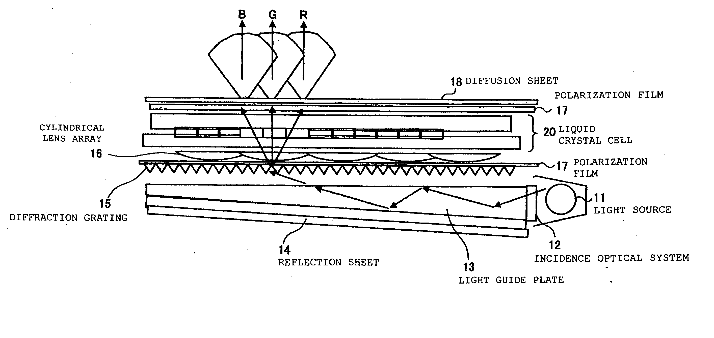
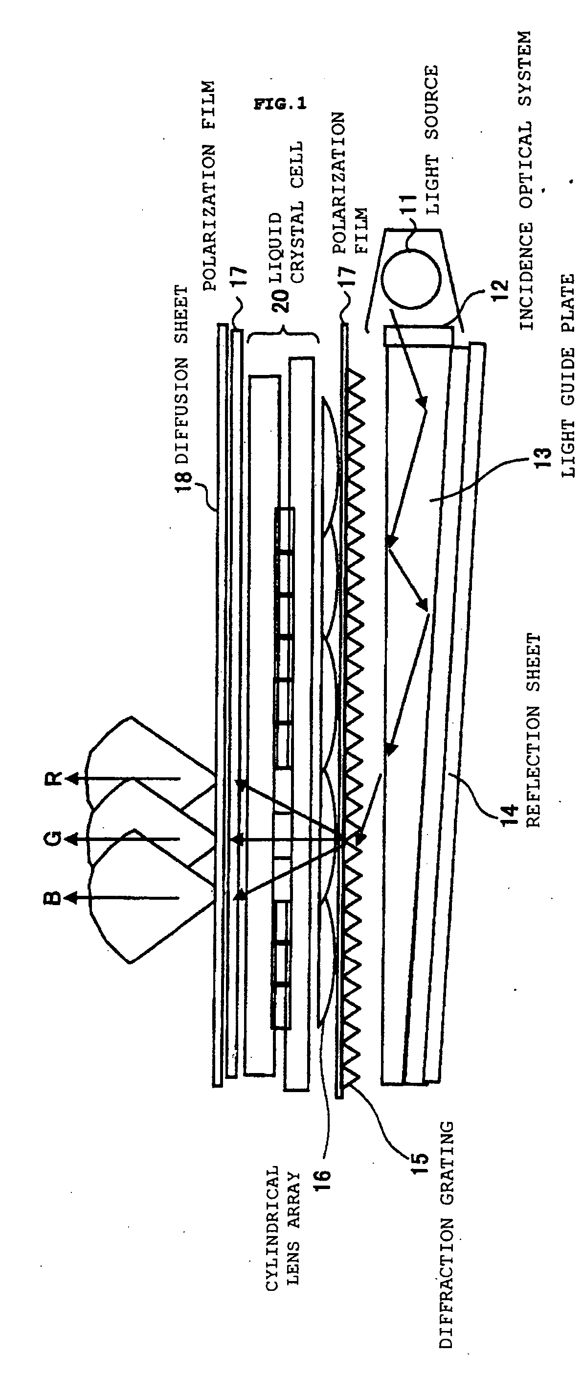
FIG. 1 is a view showing a configuration of a color filterless liquid crystal display device (color filterless and direct view liquid crystal display device) to which this embodiment is applied. This color filterless liquid crystal display device includes a light source 11 using, for example, a straight white fluorescent tube, an incidence optical system 12 a guiding light from the light source 11, a light guide plate 13 having, for example, a wedge shape, a reflection sheet 14, and a diffraction grating 15 as a spectral element separating the incident white light into a red (R) light, a green (G) light and a blue (B) light. Moreover, this liquid crystal display includes a liquid crystal cell 20, a cylindrical lens array 16 as an optical element (condensing element) provided with a plurality of cylindrical lenses or the like, polarization films 17, and a diffusion film 18. The liquid crystal cell 20 includes a liquid crystal layer inserted between two glass substrates as will be des...

embodiment 2

Next, as Embodiment 2, an example using a microlens structure will be described. Note that, for similar functions to those in Embodiment 1 described for the microprism structure, the same reference numerals will be used, and here, detailed description thereof will be omitted.

In the conventional color filterless liquid crystal projection device, because of the viewing angle dependencies different for each color and the angle expansion by the condensing function element, a diffusion effect occurs in a process from the liquid crystal cell 20 to a projecting optical element, thus causing a problem of lowering the color reproductivity / resolution, which is caused by color mixture and blur. In order to solve this and to obtain a display image excellent in color reproductivity and clear without blur, a method of correcting in angle the light of every wavelength, which is emitted from the liquid crystal cell, into a substantially parallel light mainly directed to the frontal direction, an...


PUM

PropertyMeasurementUnit
basic angleaaaaaaaaaa
angleaaaaaaaaaa

Abstract

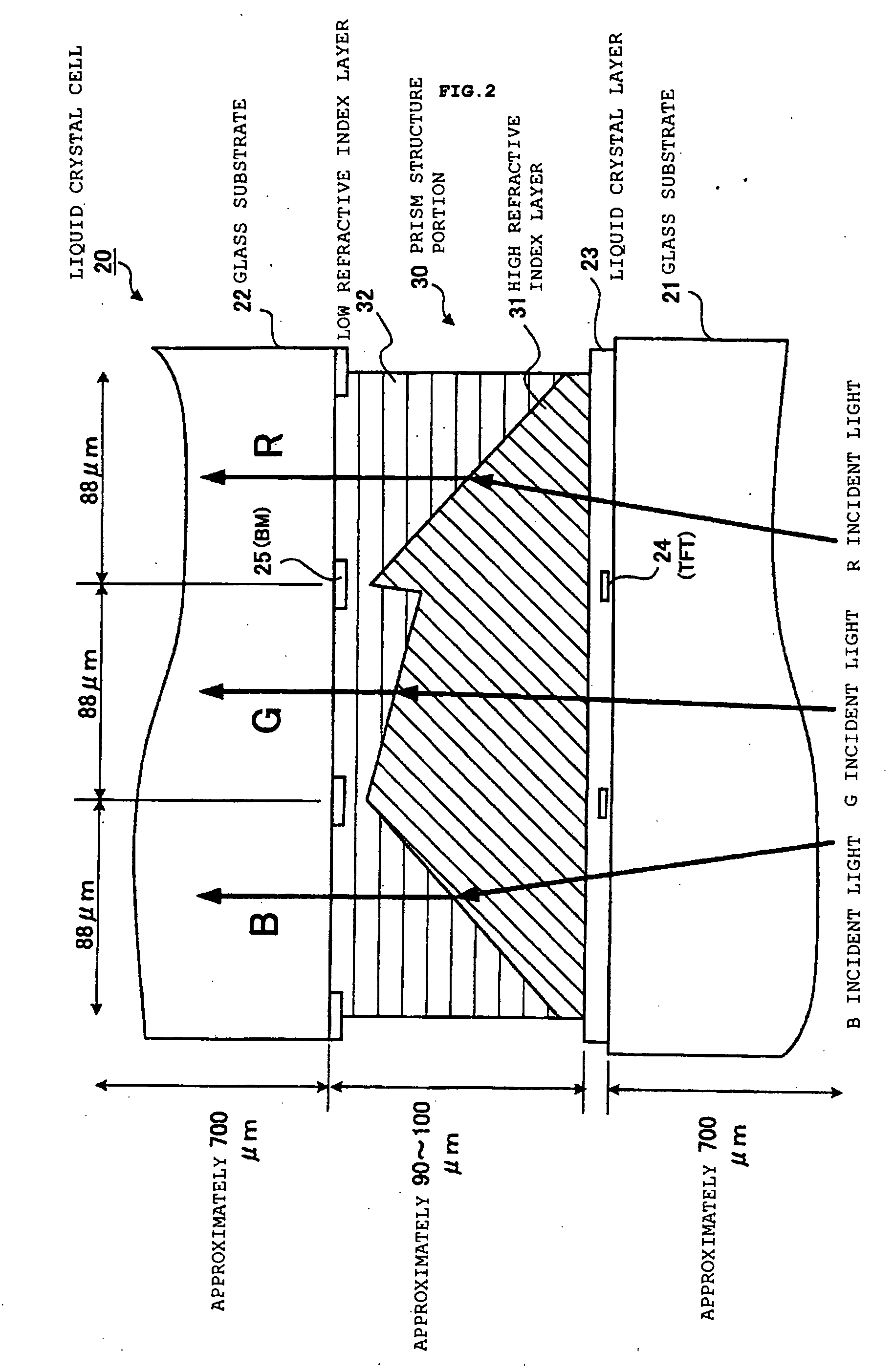
A color filterless display device performing color display for expressing one pixel by three RGB sub-pixels includes: a light source; a diffraction grating for separating a light irradiated from this light source into lights of a plurality of wavelength regions; a cylindrical lens array for receiving the separated light and condensing the light while corresponding to each of the sub-pixels; and a liquid crystal cell including a structure portion for correcting an angle of the condensed light for all sub-pixels, wherein, in the structure portion of this liquid crystal cell, a side onto which a light from the cylindrical lens array is made incident is made of a high refractive index layer, an emitting side from which the light is emitted is made of a low refractive index layer, and a Fresnel-type microprism structure is formed by the high refractive index layer and the low refractive index layer.

Description

FIELD OF THE INVENTION The present invention relates to a color display device and the like, and more specifically, to a color display device capable of color display without using color filters, and the like. BACKGROUND OF THE INVENTION A color liquid crystal display device widely used in recent years among color display devices users has several hundred thousands to several million pixels. Each pixel is composed of R (red), G (green) and B (blue) sub-pixels. In order to display the R, G and B for each sub-pixel, R, G and B color filters are used in many cases, and a full color image is obtained by combining displays of the sub-pixels using these color filters. In the case of using such color filters, two-thirds of a light is absorbed by these color filters, and theoretically, approximately one-third of the light is only usable. In this connection, a color filterless display device performing color display without using the color filters is under study. The following documents a...

Claims


Application Information

Patent Timeline
Patent Type & Authority Applications(United States)
IPC IPC(8): G02B5/00F21V8/00G02B3/00G02B5/04G02B5/18G02F1/1335G02F1/13357G09F9/00
CPCG02B6/0053G02F1/133621G02F1/133526
Inventor NUMATA, HIDETOSHIONO, SHINYAYAMADA, FUMIAKITAIRA, YOICHI
Owner IBM CORP
Learn More