

Control apparatus
a liquid crystal display panel and control apparatus technology, applied in the direction of instruments, static indicating devices, etc., can solve the problems of blurred image display for users, unclear image,
- Summary
- Abstract
- Description
- Claims
- Application Information
AI Technical Summary
Benefits of technology
Problems solved by technology
Method used
Image

Examples
first embodiment
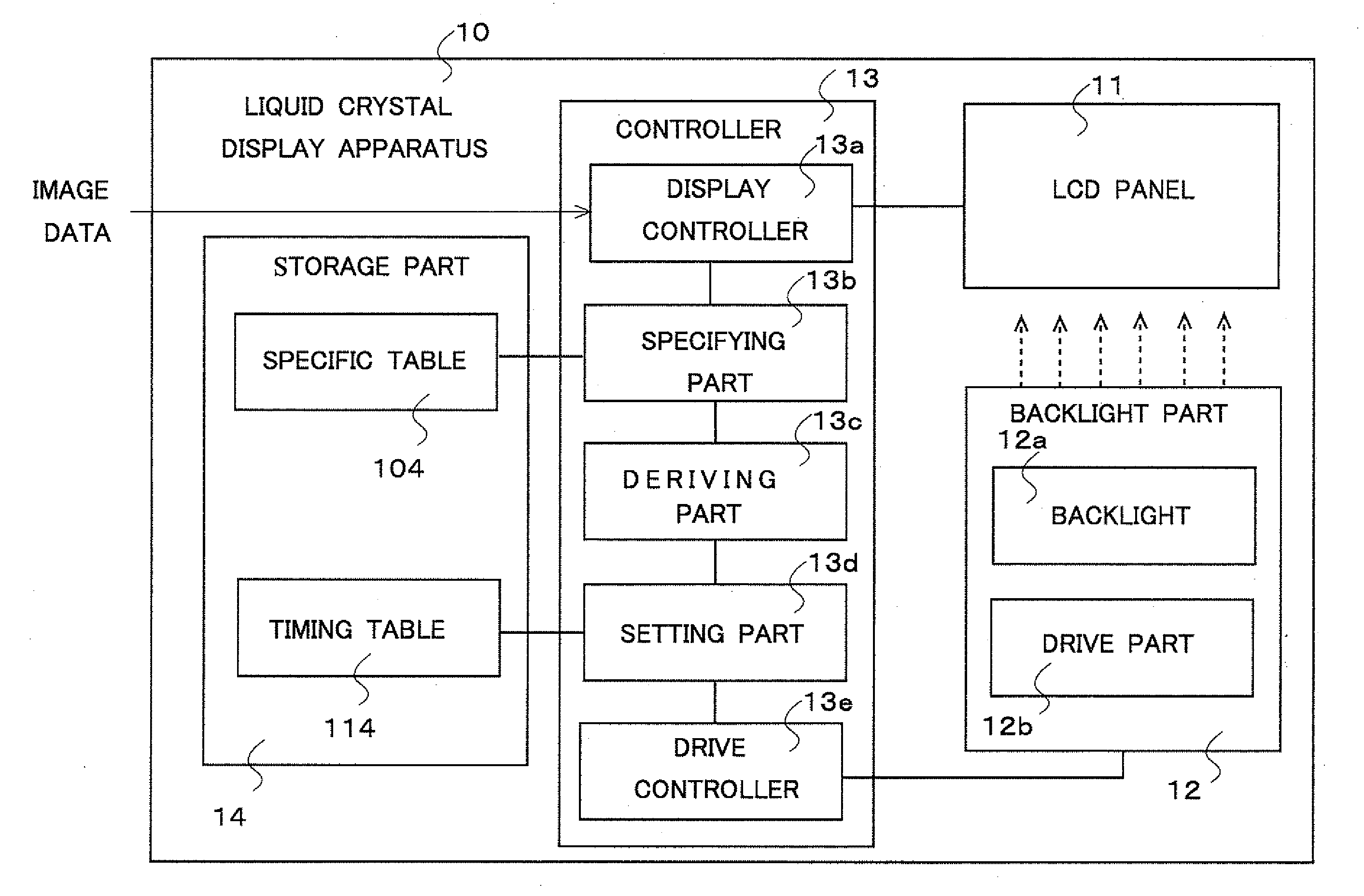
[0049]FIG. 2 is a block diagram illustrating a configuration of a liquid crystal display apparatus 10 in this embodiment. The liquid crystal display apparatus 10 includes a liquid crystal display (LCD) panel 11, a backlight part 12, a controller 13, and a storage part 14. Moreover, the controller 13 includes a display controller 13a, a specifying part 13b, a deriving part 13c, a setting part 13d, and a drive controller 13e. Furthermore, the backlight part 12 includes a backlight 12a and a drive part 12b. In addition, the storage part 14 stores a specific table 104 and a timing table 114.
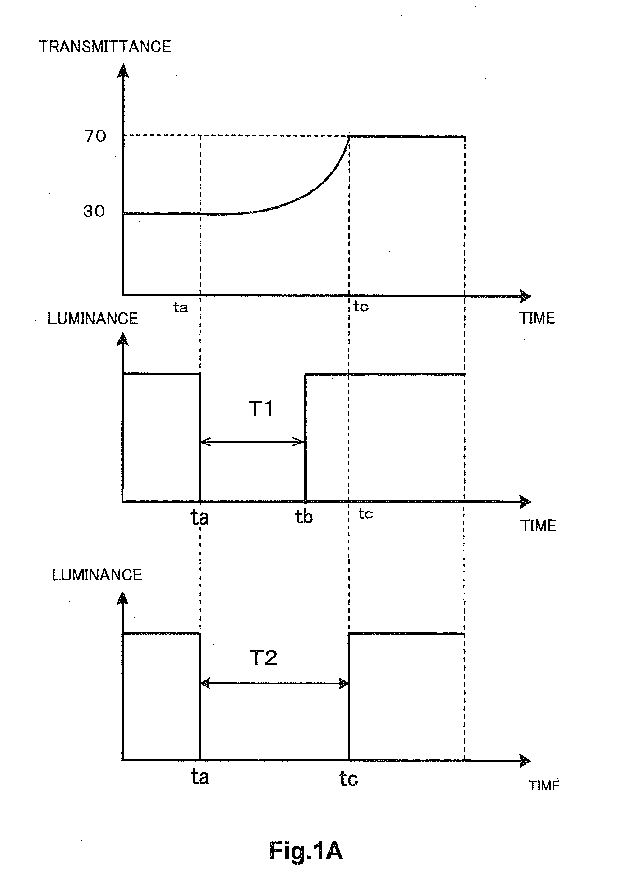
[0050]The LCD panel 11 is an image display that displays an image by partially blocking or transmitting light provided from the backlight 12a, by using liquid crystal molecules. The LCD panel 11 performs a process of changing a pre-change transmittance of light at each of the plural pixels of the LCD panel 11 to a post-change transmittance (a target transmittance). More concretely, the pre-change tra...
second embodiment
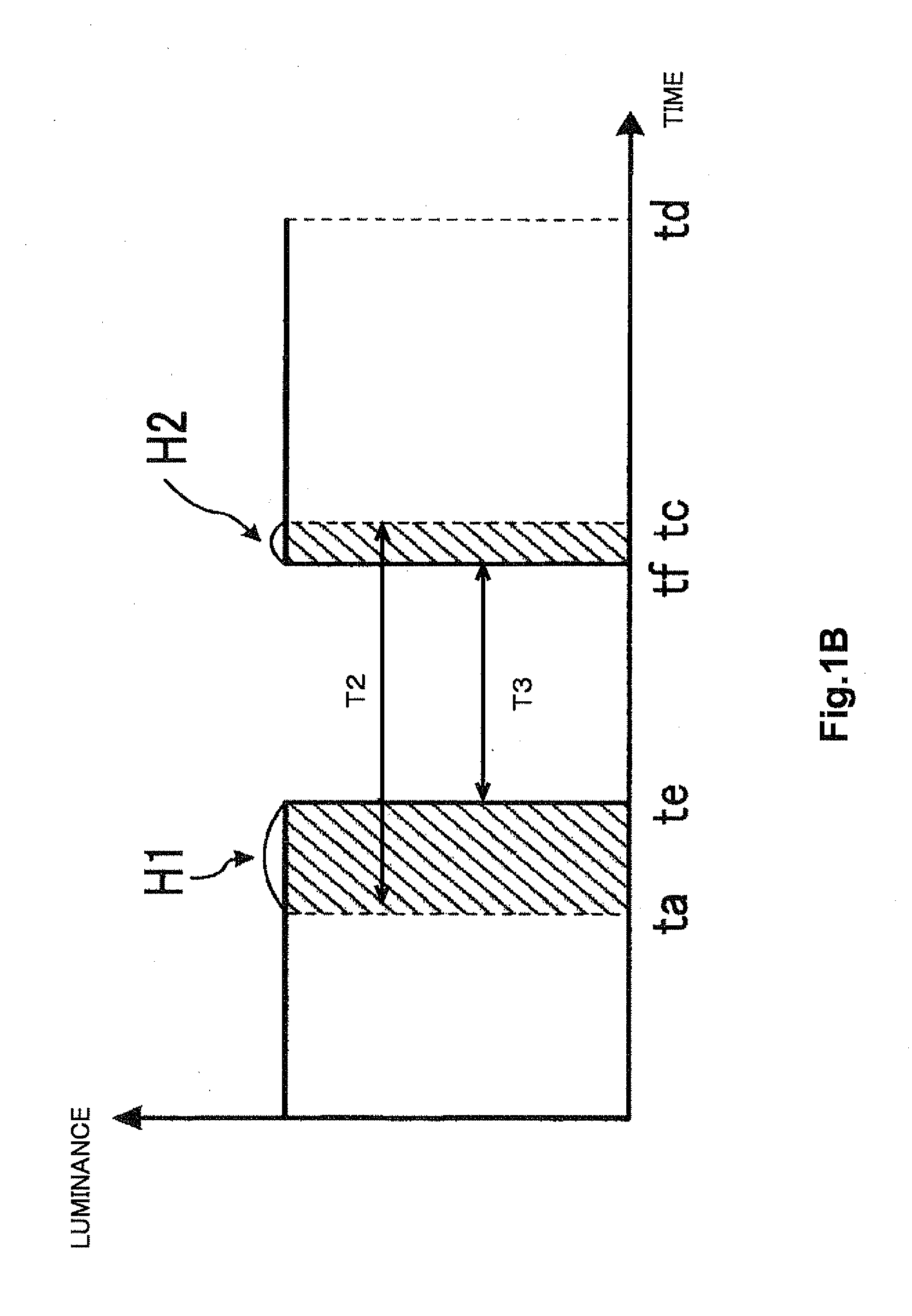
[0092]The following is a difference between a second embodiment and the first embodiment. In the first embodiment, the duration of the unlit time period of the backlight 12a is changed every time when an image in a frame displayed on the LCD panel 11 is changed. However, when the duration of the unlit time period is changed for each image in a frame, the duration of the lighting time period of the backlight 12a is also changed for each image in a frame. As a result, a sum value of the luminance of the backlight 12a in one lighting time period is changed for each image in a frame. Thus there is a case where user visibility to see the image is reduced. Therefore, in the second embodiment, the sum value of the luminance (sum luminance value) of a backlight 12a in one lighting time period is not changed for each image in a frame but is kept constant. The configuration and the process in the second embodiment is substantially the same as the configuration and the process in the first emb...
third embodiment
[0099]The following is a difference between a third embodiment and the first embodiment. In the first embodiment, the unlit time period of the backlight 12a is changed for each image in a frame. On the other hand, in the third embodiment, a duration of an unlit time period of the backlight 12a is not changed but fixed, and the unlit time period is moved on a time axis, in other words, a lighting time period is moved on the time axis. Thus a clear image is displayed for the user. The configuration and the process in the third embodiment is substantially the same as the configuration and the process in the first embodiment, except the move of a lighting time period on the time axis. Therefore, a description of a same portion in the configuration and in the process is omitted.
[0100]FIG. 9A illustrates an example of a process performed in a case where a duration of a lighting time period Td of a backlight 12a is fixed. Moreover, FIG. 9B illustrates a timing table 114c.
[0101]Having the ...
PUM
 Abstract
Description
Claims
Application Information