Image display device
a display device and image technology, applied in optics, instruments, electrical devices, etc., can solve the problem of lower luminance of display images, and achieve the effect of high luminance images
- Summary
- Abstract
- Description
- Claims
- Application Information
AI Technical Summary
Benefits of technology
Problems solved by technology
Method used
Image
Examples
first embodiment
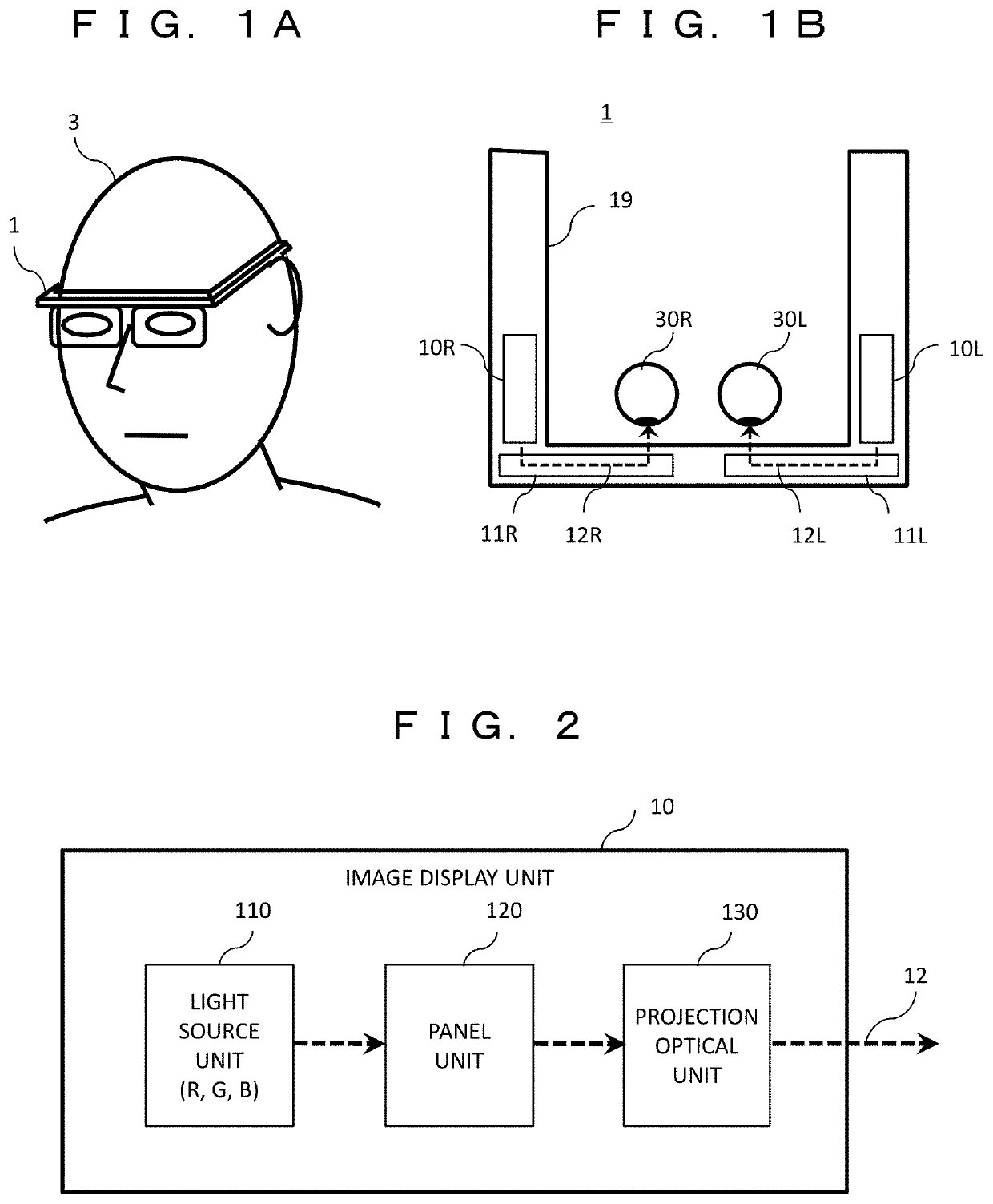
[0030]FIG. 1A and FIG. 1B are diagrams illustrating a usage form and a schematic configuration of a binocular HMD. FIG. 1A illustrates a usage form of a binocular HMD 1. A user 3 wears the binocular HMD 1 on the head and visually recognizes left and right images displayed by the binocular HMD 1.
[0031]FIG. 1B is a schematic configuration diagram of the binocular HMD 1 viewed from above the user 3. The binocular HMD 1 includes a right eye image display unit 10R and a left eye image display unit 10L, a right eye wave guide unit 11R and a left eye wave guide unit 11L, and a holding unit 19. The holding unit 19 is a housing for holding all or some of constituent parts of the binocular HMD 1. The user 3 wears holding unit 19 on the head and uses the binocular HMD 1.
[0032]The right eye image display unit 10R and the left eye image display unit 10L generate right eye and left eye images, respectively, and emit image light 12R and image light 12L. The emitted image light 12R and image light ...
second embodiment
[0085]In a second embodiment, the maximum value Tlight of the length of the lighting period of one light source may be equal to or larger than the length Twait of the standby period of the panel unit associated with each color image display (Tlight≥Twait). Accordingly, it is possible to increase the lighting time of the light source in the period of one frame and to improve the luminance of the binocular HMD 1. However, when Tlight≥Twait, there is a period in which the light source of the right eye image display unit 10R and the light source of the left eye image display unit 10L are turned on at the same time within the period in which the image of one frame is displayed (that is, the sum Tsum of the overlap lighting period>0). Therefore, in the present embodiment, the delay time is set so that the sum Tsum of the overlap lighting period is minimized, and a configuration of the power source 16 is changed to stand even when the peak of the current source supplied to the light source...
third embodiment
[0115]In a third embodiment, before and after the right eye image display unit 10R displays an image of a first color in the field sequential driving, the left eye image display unit 10L displays images of second and third colors different from the first color. In other words, the right eye image display unit 10R and the left eye image display unit 10L are configured not to consecutively display images of the same color. Accordingly, it is possible to reduce the color break.
[0116]FIGS. 12A and 12B are diagrams illustrating an image display operation in the present embodiment, FIG. 12A illustrates a time sequence, and FIG. 12B illustrates the sum Tsum of the overlap lighting period. Here, the length Twait of the standby period of the panel unit associated with each color image display is equal to or larger than the maximum length Tlight of the lighting period of the light source (Twait≥Tlight).
[0117]In FIG. 12A, the order of colors displayed by the field sequential driving is common ...
PUM
| Property | Measurement | Unit |
|---|---|---|
| delay time Td2 | aaaaa | aaaaa |
| delay time | aaaaa | aaaaa |
| delay time Td2 | aaaaa | aaaaa |
Abstract
Description
Claims
Application Information
 - R&D
- Intellectual Property
- Life Sciences
- Materials
- Tech Scout
- Unparalleled Data Quality
- Higher Quality Content
- 60% Fewer Hallucinations
Browse by: Latest US Patents, China's latest patents, Technical Efficacy Thesaurus, Application Domain, Technology Topic, Popular Technical Reports.
© 2025 PatSnap. All rights reserved.Legal|Privacy policy|Modern Slavery Act Transparency Statement|Sitemap|About US| Contact US: help@patsnap.com


