
Imaging apparatus

Inactive Publication Date: 2007-10-18
FUJIFILM CORP
View PDF20 Cites 13 Cited by
  • Summary
  • Abstract
  • Description
  • Claims
  • Application Information

AI Technical Summary

Benefits of technology

[0006]The present invention has been made in view of such circumstances and has an object of providing an imaging apparatus that is capable of accurate focusing detection and / or exposure control even in a low-light environment.

Problems solved by technology

This leads to problems of reduction of resolution mainly in the vertical direction and hence reduction of accuracy of focusing detection and / or exposure control.

Method used


Image

  • Imaging apparatus
  • Imaging apparatus
  • Imaging apparatus

Examples


first embodiment

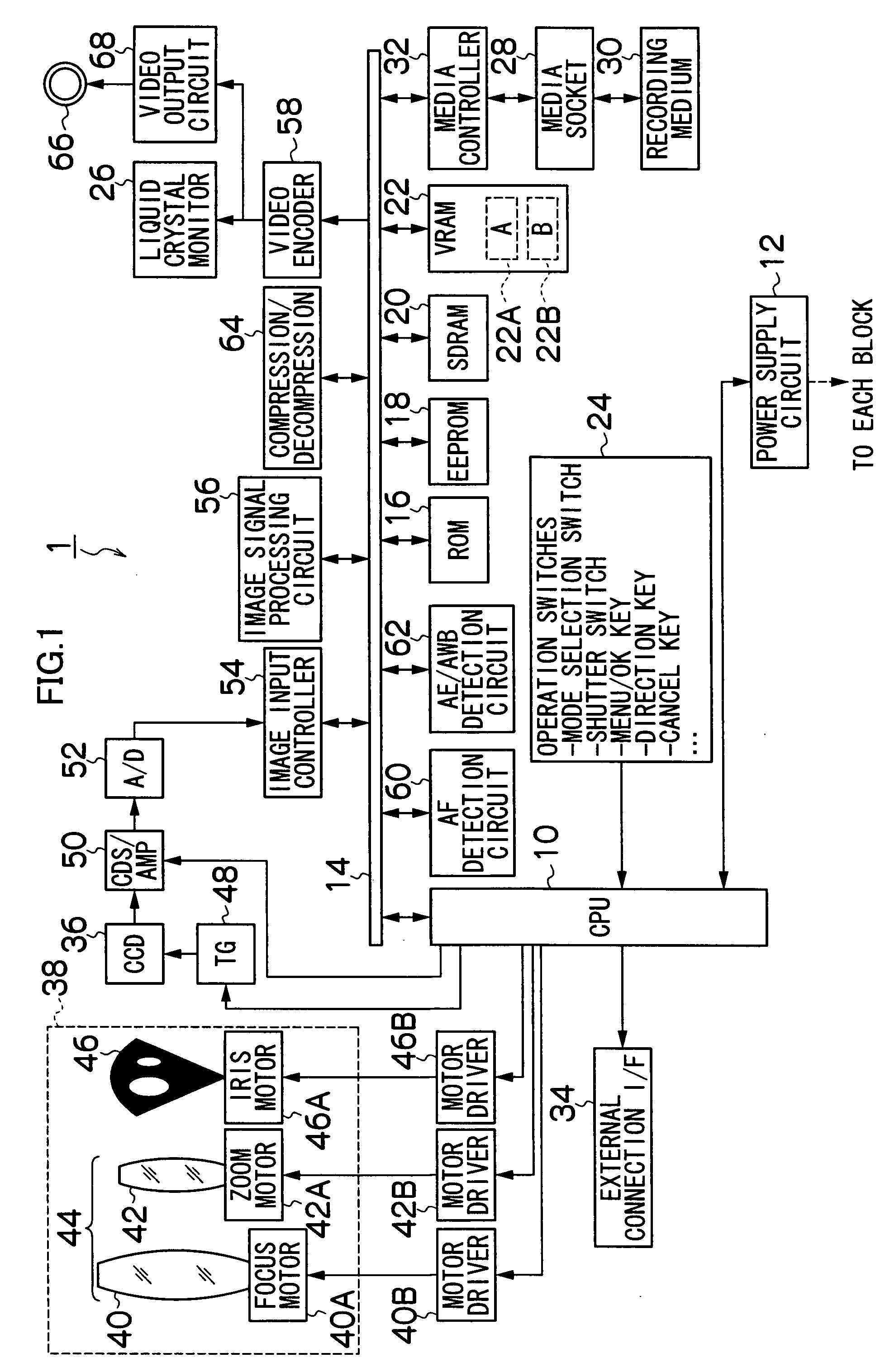
[0110]FIG. 12 shows a flowchart illustrating an image output adjustment method. First, while a through-movie picture is displayed on the liquid crystal monitor 26, the CPU 10 determines whether the pixel addition mode is G-pixel double addition mode (step S100). If the pixel addition mode is G-pixel double addition mode (YES at step S100), it is determined whether the pixel addition mode which was set in generating the image of the frame preceding the through-movie picture was also G-pixel double addition mode (step S102). The time at which normal addition mode is changed to G-pixel double addition mode is stored in the memory 20 by the CPU 10, for example. If the pixel addition mode for generating the image of the previous frame was also G-pixel double addition mode (YES at step S102), processing is terminated. On the other hand, if the pixel addition mode for generating the image of the previous frame was not normal addition mode as illustrated at time T20 in FIG. 13 (NO at step S...

second embodiment

[0111]FIG. 14 shows a flowchart illustrating the image output adjustment method. First, while a through-movie picture is displayed on the liquid crystal monitor 26, the CPU 10 determines whether the pixel addition mode is G-pixel double addition mode (step S110). If the pixel addition mode is G-pixel double addition mode (YES at step S110), it is determined whether the pixel addition mode which was set in generating the image of the frame preceding the through-movie picture was also G-pixel double addition mode (step S112). The time at which normal addition mode is switched to G-pixel double addition mode is stored in the memory 20 by the CPU 10, for example. If the pixel addition mode which was set in generating the image of the previous frame was also G-pixel double addition mode (YES at step S112), processing is terminated. On the other hand, if the pixel addition mode which was set in generating the image of the previous frame was not normal addition mode (NO at step S112), digi...

third embodiment

[0112]FIG. 15 shows a flowchart illustrating the image output adjustment method. First, while a through-movie picture is displayed on the liquid crystal monitor 26, the CPU 10 determines whether the pixel addition mode is G-pixel double addition mode (step S120). If the pixel addition mode is G-pixel double addition mode (YES at step S120), it is determined whether the pixel addition mode which was set in vertical transfer of pixel signals when generating the image of the frame preceding the through-movie picture was also G-pixel double addition mode (step S122). The time at which normal addition mode is switched to G-pixel double addition mode is stored in the memory 20 by the CPU 10, for example. If the pixel addition mode for generating the image of the previous frame was also G-pixel double addition mode (YES at step S122), processing is terminated. However, if the pixel addition mode for generating the image of the previous frame was not normal addition mode (NO at step S122), ...


PUM


Abstract

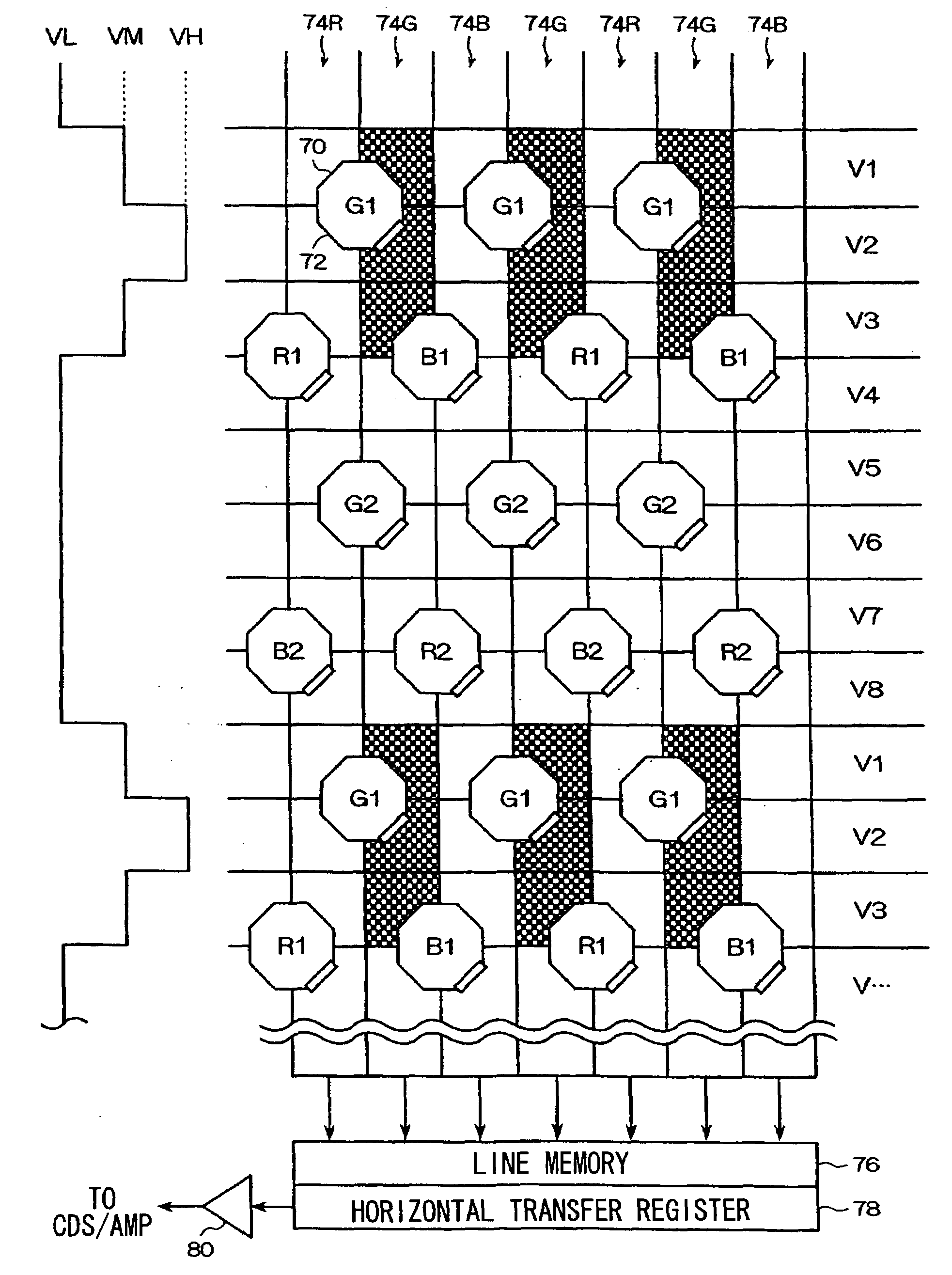
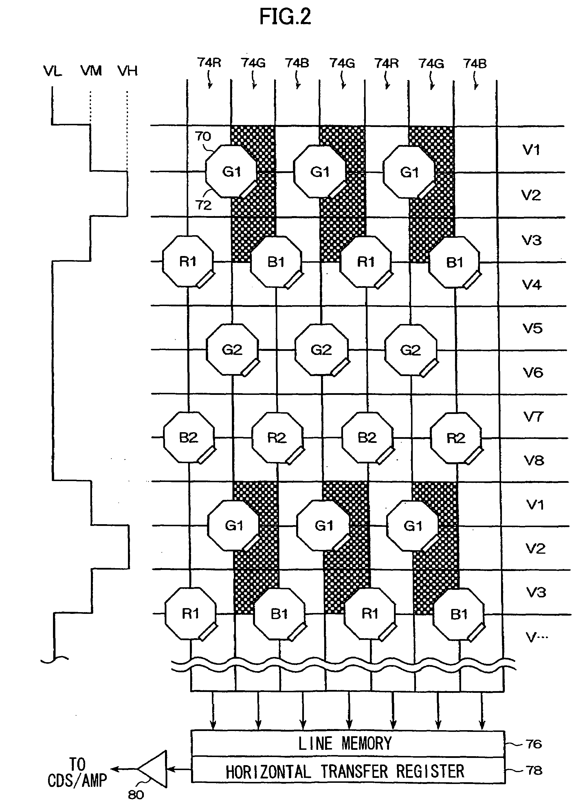
An imaging apparatus, comprising image pickup elements for obtaining image signals and a control device which control read-out of image signals from the image pickup elements, whereinthe image pickup elements comprise:light receiving elements which separate incident light into R, G and B colors and photoelectrically convert the incident light separated into the individual colors to obtain image signals including R, G and B signals corresponding to each of the colors;a vertical transfer channel for vertically transferring an image signal read out from the light receiving elements; anda horizontal transfer channel for horizontally transferring the vertically transferred image signal,the control device comprises:a read-out control device which applies a reading pulse to the light receiving elements to control read-out of the image signal from the light receiving elements;a vertical transfer control device which controls vertical transfer of an image signal read out onto the vertical transfer channel;a horizontal transfer control device which controls horizontal transfer of an image signal read out onto the horizontal transfer channel; anda driving control device which controls the read-out control device and the vertical transfer control device so that the R and B signals are each vertically added for a first number of vertical addition pixels and the G signals are vertically added for a second number of vertical addition pixels that is larger than the first number of vertical addition pixels.

Description

BACKGROUND OF THE INVENTION[0001]1. Field of the Invention[0002]The present invention relates to an imaging apparatus, and more particularly, to an imaging apparatus that includes solid-state image pickup elements.[0003]2. Description of the Related Art[0004]A solid-state imaging apparatus has been proposed that uses a line memory to perform vertical and horizontal addition of signal charge when reading out signal charge accumulated in pixels of solid-state image pickup elements (see Japanese Patent Application Laid-Open No. 2003-264844).[0005]For example, with a camera capable of high-sensitivity picture taking, when its focus is adjusted in a low-light environment, pixels that are vertically added will be increased in order to obtain luminance required for focusing. This leads to problems of reduction of resolution mainly in the vertical direction and hence reduction of accuracy of focusing detection and / or exposure control.SUMMARY OF THE INVENTION[0006]The present invention has b...

Claims


Application Information

Patent Timeline
IPC IPC(8): H04N9/04H04N5/335G02B7/36G03B7/08G03B11/00G03B13/36H01L27/148H04N5/345H04N5/347H04N5/369H04N5/372H04N5/3728H04N5/376H04N9/07
CPCH04N5/23212H04N9/045H04N5/347H04N5/2352H04N23/673H04N23/72H04N25/46H04N23/84H04N25/134
Inventor KAWAI, TOMOYUKI
Owner FUJIFILM CORP
Learn More