

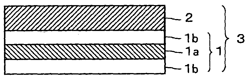
Optical film and display system
a display system and optical film technology, applied in the field of optical films, can solve the problems of narrow viewing angle, difficult to achieve perfect display of black color, retardation films conventionally known have not been able to easily realize sufficient wide viewing angles
- Summary
- Abstract
- Description
- Claims
- Application Information
AI Technical Summary
Benefits of technology
Problems solved by technology
Method used
Image

Examples
example 1
[0076] (Transparent Protective Film)
[0077] Thermoplastic saturated norbornene resin (ZEONOR1600R manufactured by ZEON) was fed to single screw extruder, subsequently extruded at 275 to 290.degree. C. to obtain a transparent protective film having a thickness of 50 .mu.m. The transparent protective film thus obtained showed 4 nm of in-plane retardation Re.sub.2 and 20 nm of thickness direction retardation Rth.
[0078] (Polarizing Plate)
[0079] The above-mentioned transparent protective film was laminated to both sides of a film (polarizer: 20 .mu.m), in which iodine was absorbed to a poly vinylalcohol based film and was subsequently stretched, using an adhesive to produce a polarizing plate.
[0080] (Optical Film)
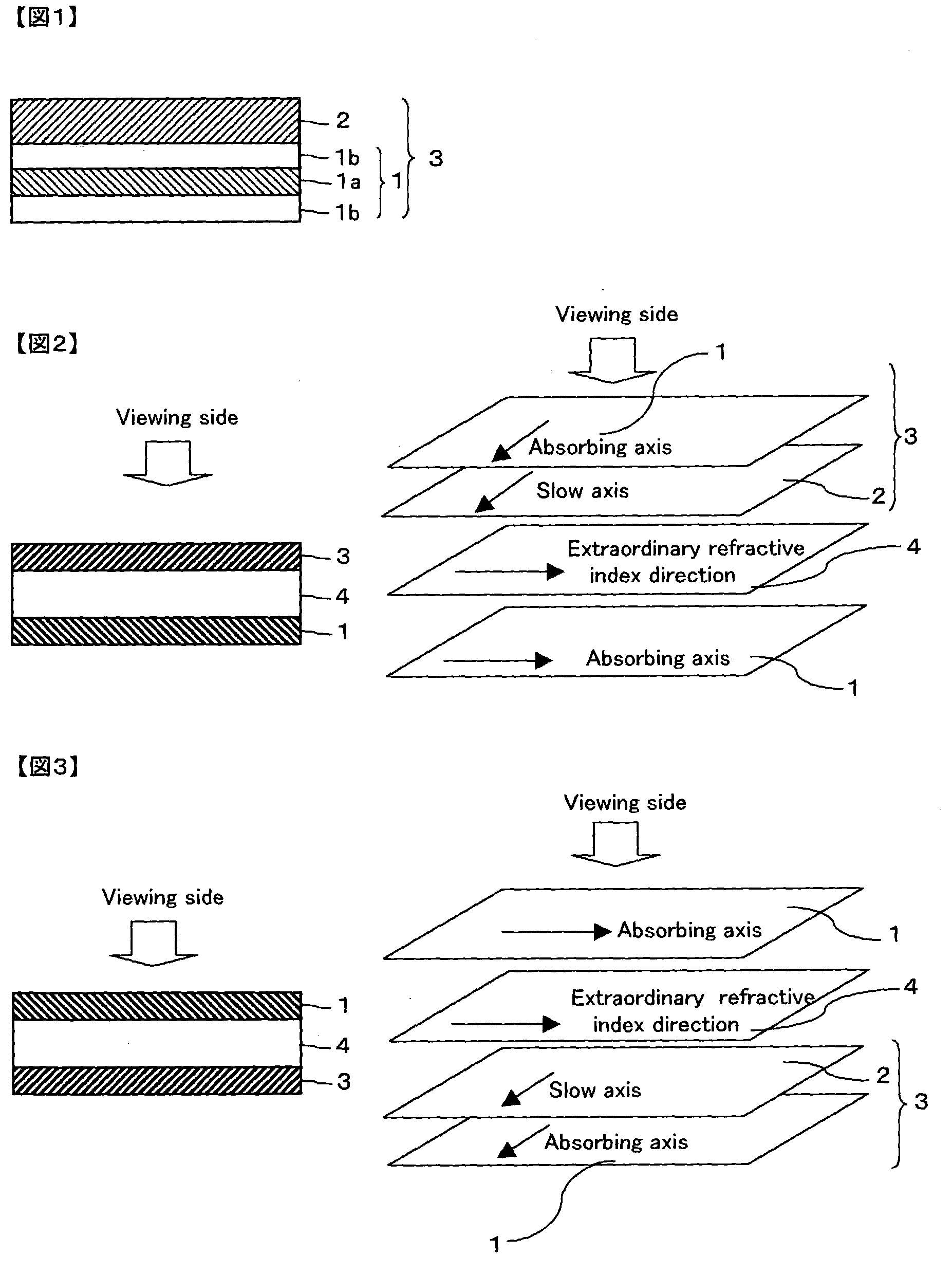
[0081] A polycarbonate film was stretched and a retardation film having a thickness of 60 .mu.m, an in-plane retardation Re.sub.1 of 260 nm, and Nz=0.5 was obtained. This retardation film and the above-mentioned polarizing plate were laminated using a pressure sensitive adhesive ...
example 2
[0086] (Transparent Protective Film)
[0087] Thermoplastic saturated norbornene resin (ARTON manufactured by JSR) was dissolved in methylene chloride to a solution. Subsequently, the solution was applied to casting method to obtain a transparent protective film having a thickness of 40 .mu.m. The transparent protective film thus obtained showed 4 nm of in-plane retardation Re.sub.2 and 22 nm of thickness direction retardation Rth.
[0088] (Polarizing Plate)
[0089] The above-mentioned transparent protective film was laminated to both sides of a film (polarizer: 20 .mu.m), in which iodine was absorbed to a poly vinylalcohol based film and was subsequently stretched, using an adhesive to produce a polarizing plate.
[0090] (Optical Film)
[0091] The polycarbonate retardation film and the above-mentioned polarizing plate were laminated using a pressure sensitive adhesive so that a slow axis of the retardation film and an absorbing axis of the polarizing plate might be parallel to produce an opti...
PUM
| Property | Measurement | Unit |
|---|---|---|
| thickness | aaaaa | aaaaa |
| thickness | aaaaa | aaaaa |
| thickness d1 | aaaaa | aaaaa |
Abstract
Description
Claims
Application Information