Support structure implant for a bone cavity

Active Publication Date: 2013-11-26
DUPUY INT LTD
View PDF29 Cites 24 Cited by
  • Summary
  • Abstract
  • Description
  • Claims
  • Application Information

AI Technical Summary

Benefits of technology

[0014]The implant of the present invention has the advantage that it can be made using conventional braiding equipment. This facilitates efficient manufacture of the implant of the present invention. It has the further advantage that the resulting implant can be made reproducibly so that its mechanical properties can be controlled. This can be important to ensure that appropriate support is provided to surrounding bone tis

Problems solved by technology

It can lead to collapse of vertebral structures.
It can lead to hip fractures.
Conditions in which a bone is weakened can give rise to severe pain and limitation of movement within a sh

Method used


Image

  • Support structure implant for a bone cavity
  • Support structure implant for a bone cavity
  • Support structure implant for a bone cavity

Examples


Embodiment Construction

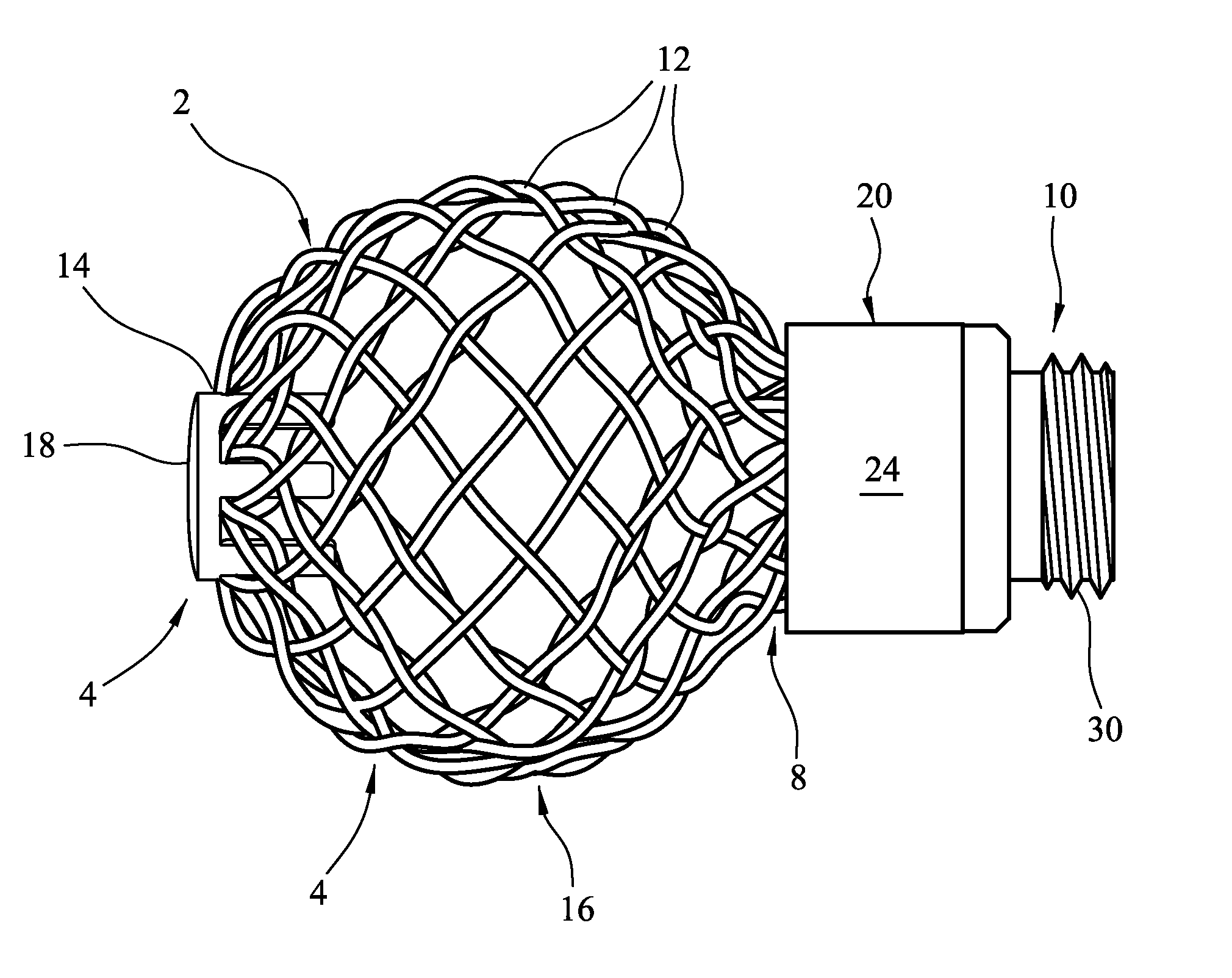
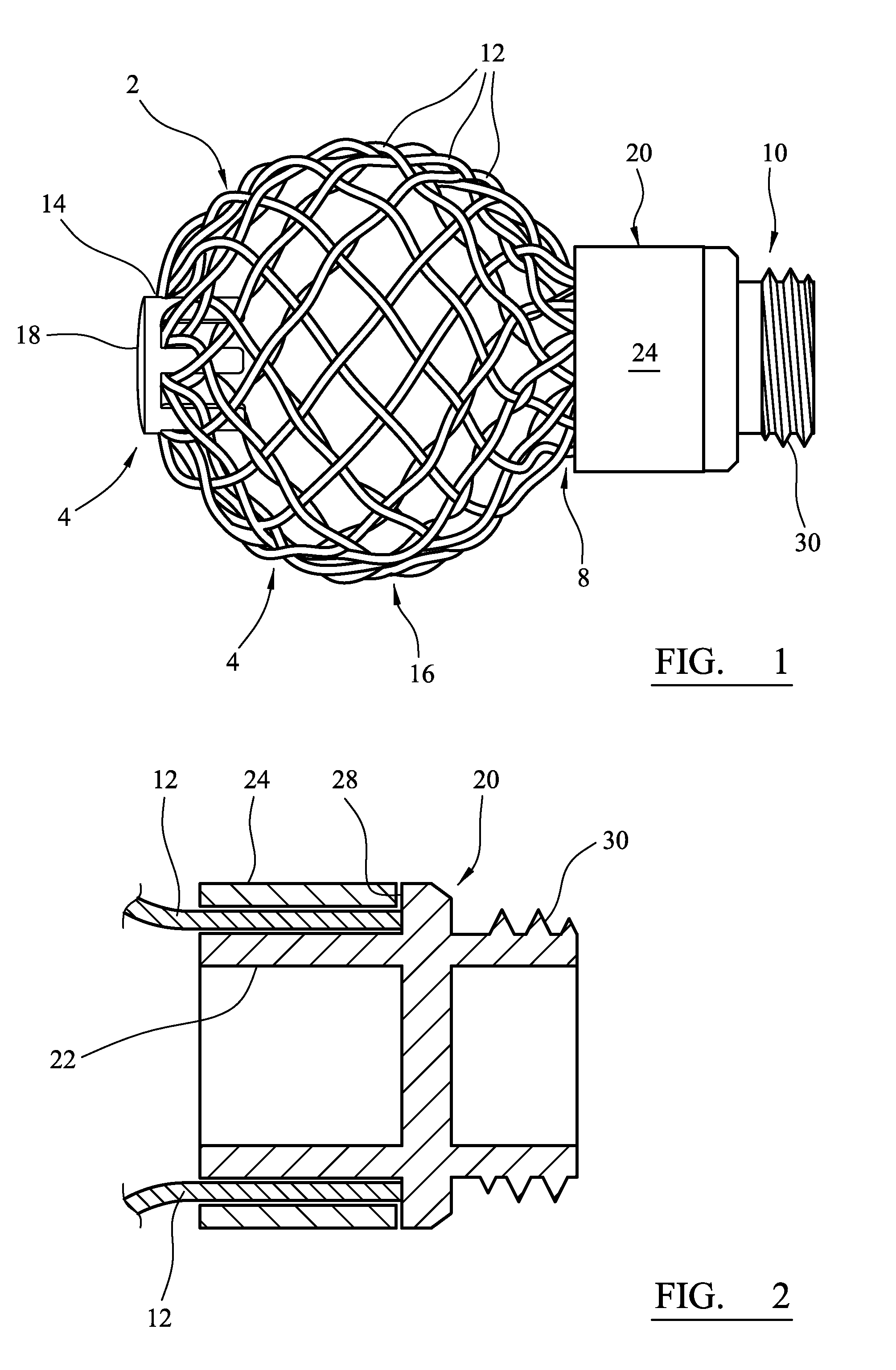
[0076]Referring to the drawings, FIG. 1 shows a stranded support structure implant 2 which can be implanted in a cavity in a bone, to support the bone which defines the cavity. The implant has a spherical portion 4 which is rounded at a first end 6 of the implant, and a cylindrical throat portion 8 at a second end 10 of the implant.

[0077]The implant 2 is formed from twelve wires 12 which are formed from a nickel titanium shape memory alloy which has been treated so that it exhibits enhanced elastic properties. The wires have a diameter of 0.5 mm.

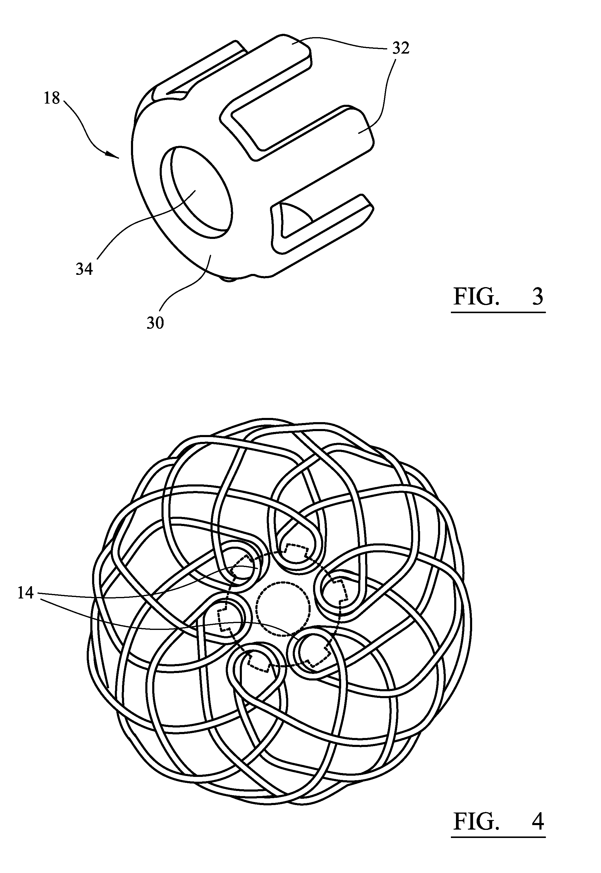
[0078]Each of the wires is formed into a loop 14. The loops are gathered together at the first end 6 of the implant so that two lengths of each wire extend from the first end. There are therefore 24 lengths of the wires extending from the first end of the implant, which are braided. The configuration of the spherical portion 4 is such that the implant flares outwardly from the first end 6 towards a wide point 16, and tapers inwardly from the...


PUM


Abstract

A support structure implant for location within a bone cavity to support the bone which defines the cavity is formed from interlaced wires which extend from a first end of the structure towards an opposite second end. The wires are formed into loops at the first end of the structure. The structure includes a clip having a plurality of fingers which extend through the loops to control the spacing between the loops.

Description

CROSS REFERENCE TO RELATED APPLICATION[0001]This application is a National Stage 35 U.S.C. 371 of International Patent Application PCT / GB2010 / 050333 filed Feb. 26, 2010.BACKGROUND OF THE INVENTION[0002]This invention relates to a support structure implant which can be located within a bone cavity to support the bone which defines the cavity. It also relates to an assembly for deploying a stranded support structure implant in a bone cavity.[0003]A cavity might be formed in a bone as a result of disease, or as a result of trauma, or as a result of a surgical procedure. Treatment of the condition can involve supporting the cavity while bone tissue regenerates within the cavity. A filler material can be provided in the cavity. This can be a curable material, for example an acrylate material similar to those used as bone cements to fix joint prosthesis components. It can be a material which stimulates regeneration of bone tissue, for example morcellised bone tissue.[0004]Avascular necros...

Claims


Application Information

Patent Timeline
IPC IPC(8): A61F2/28
CPCA61B17/68A61B17/8858A61B17/88A61F2/28
Inventor ANDERSON, JAMESGREEN, IVANMOORE, GARY
Owner DUPUY INT LTD
Why Eureka
Try Eureka