Assembled electromagnetic shielding case

Inactive Publication Date: 2013-09-12
ASKEY TECH JIANGSU +1
View PDF2 Cites 26 Cited by
  • Summary
  • Abstract
  • Description
  • Claims
  • Application Information

AI Technical Summary

Benefits of technology

[0007]It is an objective of the present invention to provide an assembled electromagnetic shielding case for prote

Problems solved by technology

In general, after being unsoldered, the shielding housing 8 becomes unusable, thereby reducing ease of use and incurring costs.
Furthermore, when covered with the shielding

Method used


Image

  • Assembled electromagnetic shielding case
  • Assembled electromagnetic shielding case
  • Assembled electromagnetic shielding case

Examples


Embodiment Construction

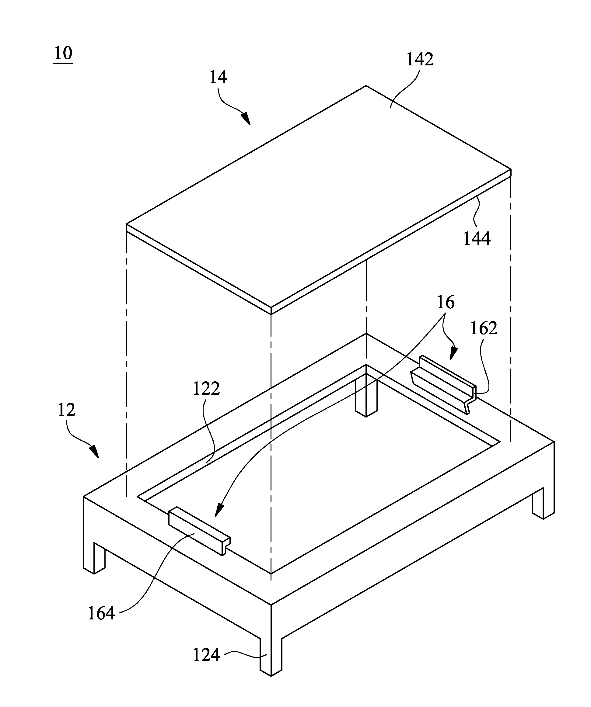
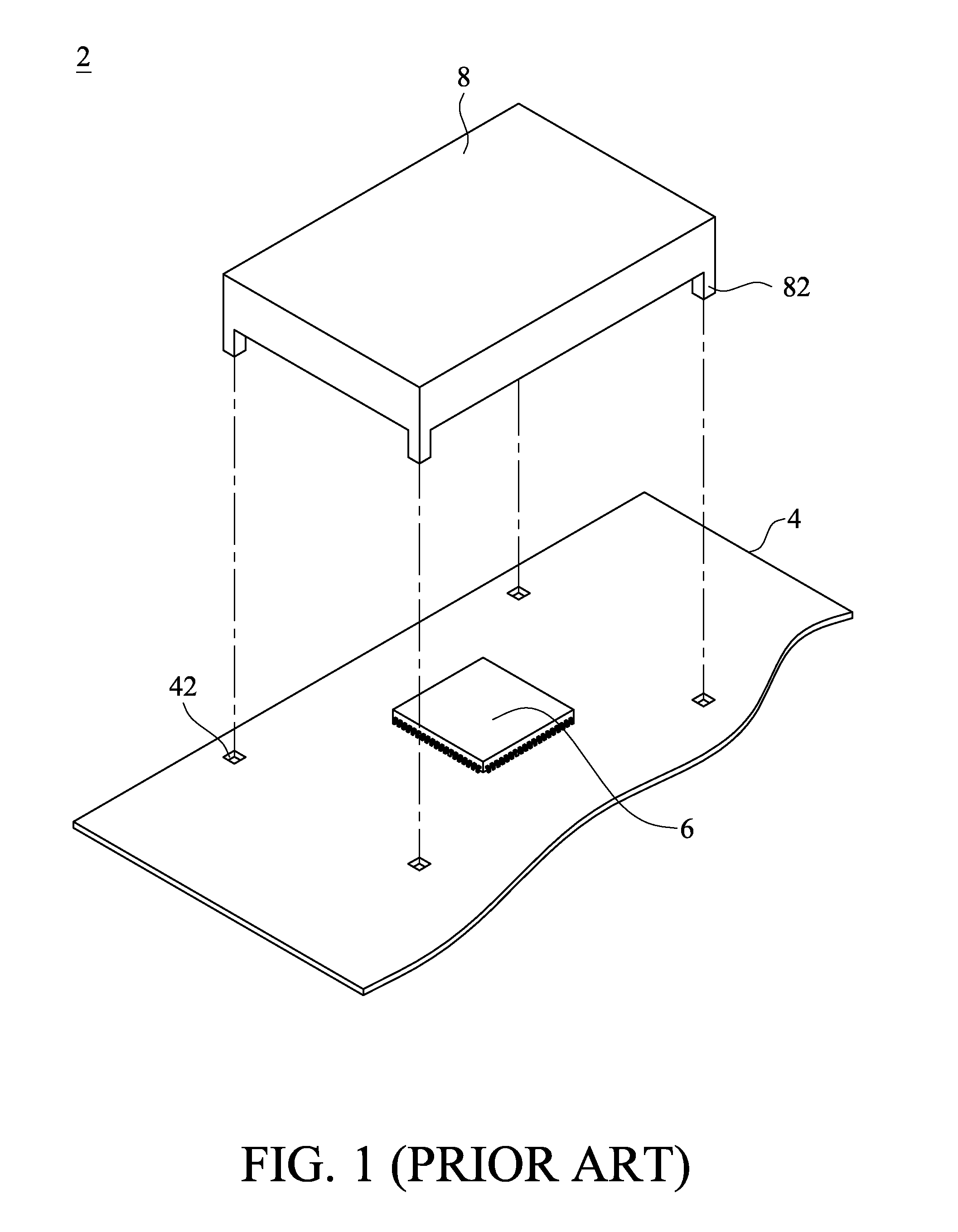
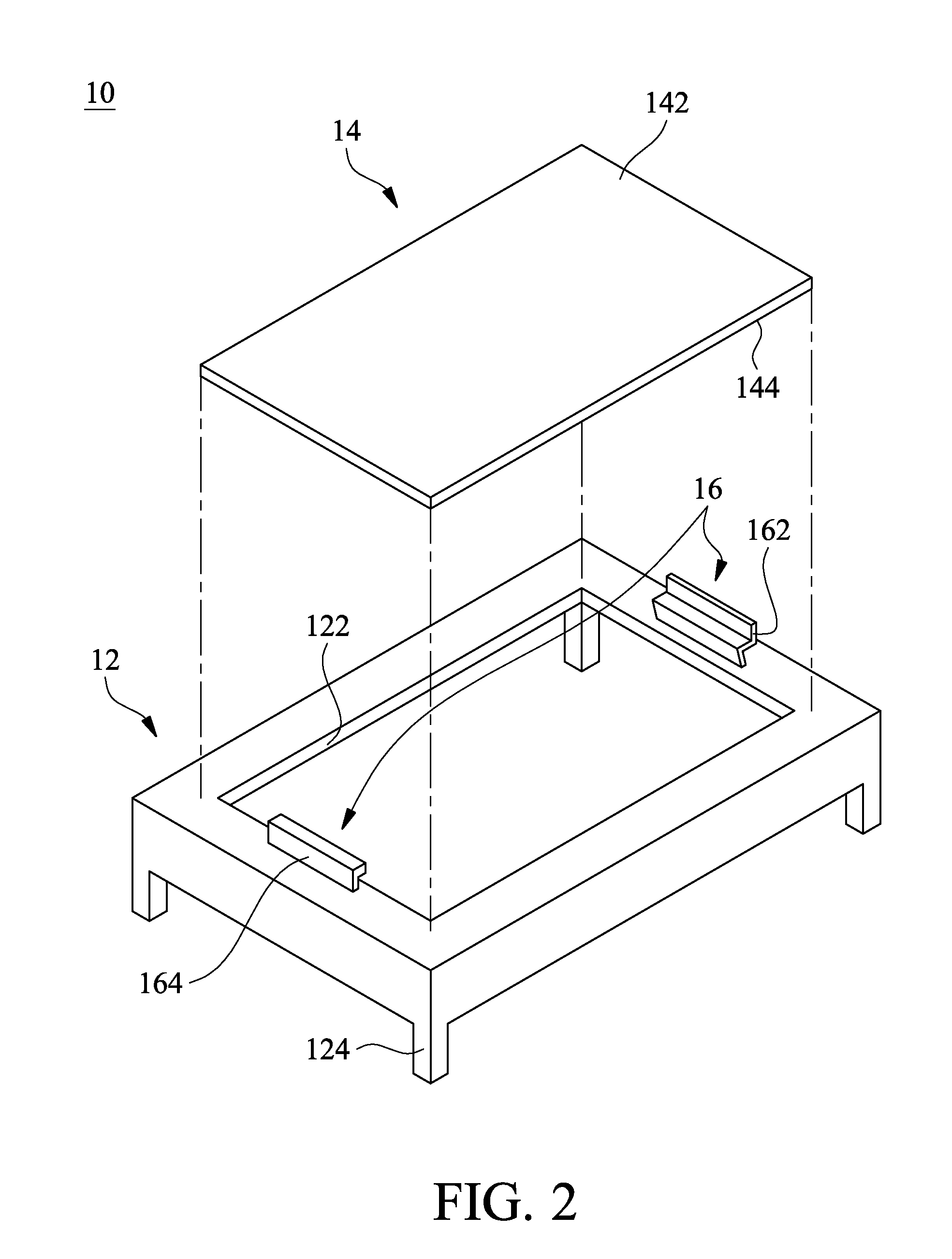
[0021]Referring to FIG. 2, there is shown a schematic view of an assembled electromagnetic shielding case 10 according to the first embodiment of the present invention. As shown in FIG. 2, the assembled electromagnetic shielding case 10 enables electromagnetic interference shielding and heat dissipation to occur to an electronic component 6 mounted on a printed circuit board 4 as shown in FIG. 9.

[0022]The assembled electromagnetic shielding case 10 comprises a body 12, a shielding element 14, and a fixing element 16. The purpose of the fixing element 16 is to couple the body 12 and the shielding element 14 together.

[0023]The body 12 has an opening 122 and an engagement portion 124. The opening 122 is designed to be closed with the shielding element 14. In the first embodiment, the opening 122 is formed on top of the body 12. For example, the opening 122 is formed, by hollowing out the body 12. Alternatively, the body 12 and the opening 122 are integrally formed as a unitary structur...


PUM


Abstract

An assembled electromagnetic shielding case conducive to electromagnetic interference shielding and heat dissipation of an electronic component on a printed circuit board includes a body, a shielding element, and a fixing element. The body has an opening and an engagement portion. The engagement portion connects the body and the printed circuit board. The shielding element has a bottom side and a heat-dissipating side opposing thereto. The shielding element closes the opening for effectuating electromagnetic interference shielding. The shielding element dissipates heat generated from the electronic component by transferring the heat from the bottom side to the heat-dissipating side for dissipating the heat. The fixing element couples the body and the shielding element. Accordingly, with the assembled electromagnetic shielding case, not only is the electronic component insusceptible to electromagnetic interference and easy to change, but it is feasible to provide highly efficient heat dissipation and a miniaturized heat dissipation structure.

Description

CROSS-REFERENCE TO RELATED APPLICATION[0001]This non-provisional application claims priority under 35 U.S.C. §119(a) on Patent Application No(s).101108099 filed in Taiwan, R.O.C. on Mar. 9, 2012, the entire contents of which are hereby incorporated by reference.FIELD OF TECHNOLOGY[0002]The present invention relates to assembled electromagnetic shielding cases, and more particularly, to an assembled electromagnetic shielding case that is easy to install and uninstall.BACKGROUND[0003]Referring to FIG. 1, according to the prior art, to protect an electronic device 2 against electromagnetic interference (EMI) and the EMI-induced deterioration of the performance of the electronic device 2, a typical protective measures taken involves soldering a shielding housing 8 to a printed circuit board 4 inside the electronic device 2 to cover a related electronic component 6 mounted on the printed circuit board 4 and coupling a plurality of pins 82 of the shielding housing 8 to a plurality of thro...

Claims


Application Information

Patent Timeline
IPC IPC(8): H05K7/20
CPCH05K9/0032H05K7/20418
Inventor LEE, WEN-HSIENLO, SHIH-POHSIEH, CHING-FENG
Owner ASKEY TECH JIANGSU
Why Eureka
Try Eureka