
Product including power supply circuit board

a technology of power supply circuit board and product, which is applied in the direction of high frequency circuit adaptation, non-resonant long antennas, instruments, etc., can solve the problems of difficult to arrange the wireless ic device on various products, the resonant frequency characteristics of the antenna can be changed, and it is difficult to implement the fine wireless ic chip. , to achieve the effect of high mounting accuracy, reduced capacitance generation between the electrodes, and easy arranging

Active Publication Date: 2009-01-08
MURATA MFG CO LTD
View PDF75 Cites 166 Cited by
  • Summary
  • Abstract
  • Description
  • Claims
  • Application Information

AI Technical Summary

Benefits of technology

The present invention provides a power supply circuit board with a stable power supply circuit that can communicate with various products. The power supply circuit board has a resonant circuit with an inductance element and a capacitance element that work together to achieve a stable frequency. The wireless communication circuit board is electrically connected to the power supply circuit board, and the radiation plate on the product helps to transmit and receive signals. The power supply circuit board can be a multilayer board or a thin film multilayer board for increased flexibility and improved performance. The technical effect of this invention is stable frequency characteristics and communication among various products.

Problems solved by technology

However, it is considerably difficult to implement the fine wireless IC chip 610 on each of the films 600 and 620 having large areas.
That is, there arises a problem in that if positional deviation is generated in implementation, resonant frequency characteristics of the antennas can be changed.
Although the possibilities for use of such a wireless IC device are infinite, it is still difficult to arrange the wireless IC device on various products since resonant frequency characteristics are changed in accordance with an arrangement state of an antenna.

Method used


Image

  • Product including power supply circuit board
  • Product including power supply circuit board
  • Product including power supply circuit board

Examples


twelfth example

of Electromagnetic Coupling Module

Refer to FIGS. 24 and 25

[0129]An electromagnetic coupling module 11 of a 12th example of a preferred embodiment is configured such that a coil electrode of a power supply circuit 56 is incorporated in a power supply circuit board 50 as shown in FIG. 24. As shown in FIG. 25, the power supply circuit board 50 includes dielectric ceramic sheets 51A to 51D which are laminated and pressure bonded with one another, and sintered, for example. The sheet 51A includes connection electrodes 52 and via-hole conductors 53a, the sheet 51B includes an inductor electrode 54a and via-hole conductors 53b and 53c, the sheet 51C includes an inductor electrode 54b, and the sheet 51D (a plurality of sheets 51) is a plain sheet.

[0130]By laminating the sheets 51A to 51D, in the coil electrode, the power supply circuit board 50 which incorporates the power supply circuit 56 including a resonant circuit constituted by a spiral inductance element and a capacitance component g...

thirteenth example

of Electromagnetic Coupling Module

Refer to FIGS. 26 and 27

[0131]An electromagnetic coupling module 1m of a 13th example of a preferred embodiment is configured, as shown in an equivalent circuit of FIG. 26, such that a power supply circuit board 10 and radiation plates 20 are capacitively coupled with each other. The power supply circuit board 10 includes a power supply circuit 16 having two LC series resonant circuits. One end of an inductance element L1 and one end of an inductance element L2 are connected to a wireless communication circuit board 5, and the other end of the inductance element L1 and the other end of the inductance element L2 are connected to capacitor electrodes 72a and 72b (refer to FIG. 27), respectively, which are included in capacitance elements C1 and C2, respectively, which are arranged on the power supply circuit board 10. Note that one end of one of the radiation plates 20 and one end of the other of the radiation plates 20 serve as capacitor electrodes i...

first preferred embodiment

Refer to FIG. 41

[0162]As shown in FIG. 41, a first preferred embodiment preferably is applied to an automobile 200, and a car body 201 of the automobile 200, which is made of a steel plate, for example, is used as a radiation plate. The automobile 200 preferably includes an ETC transmitter / receiver 205, a navigation device 206 including a television set, and a car radio 207. Here, an electromagnetic coupling module 1 which includes a wireless communication circuit board (modem) incorporating reception circuits (and a transmission circuits as needed) which receive signals for the respective devices (such as an ETC signal, a GPS signal, a television signal, and a radio signal) is attached to the steel plate portion of the car body 201, and the power supply circuit is connected to the steel plate portion (radiation plate) through electromagnetic field coupling. The reception circuits (and the transmission circuits as needed) for the respective devices are electrically connected to the ...


PUM

PropertyMeasurementUnit
frequencyaaaaaaaaaa
thicknessaaaaaaaaaa
thicknessaaaaaaaaaa

Abstract

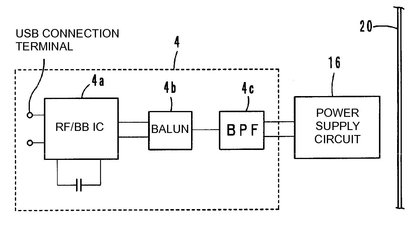
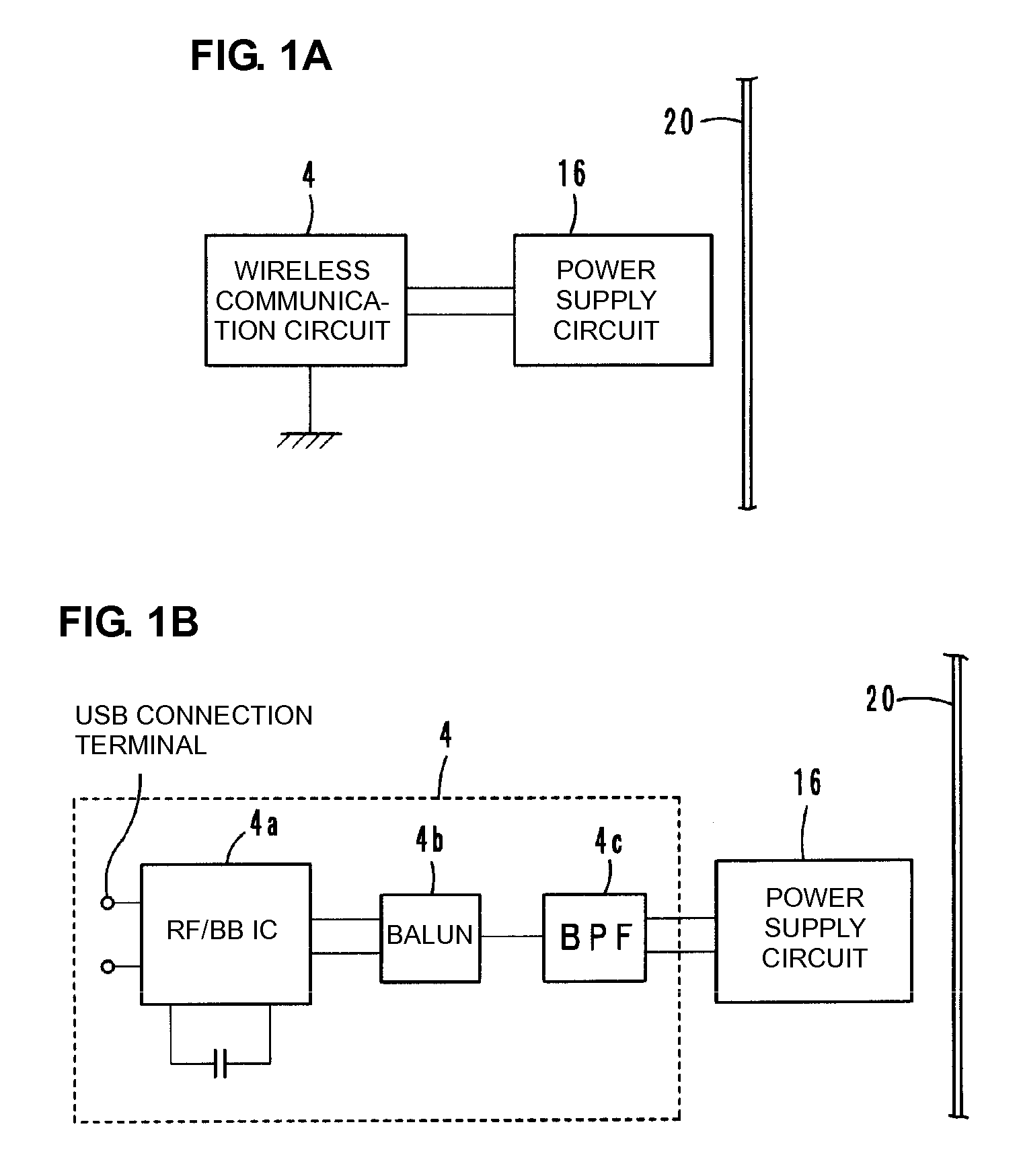
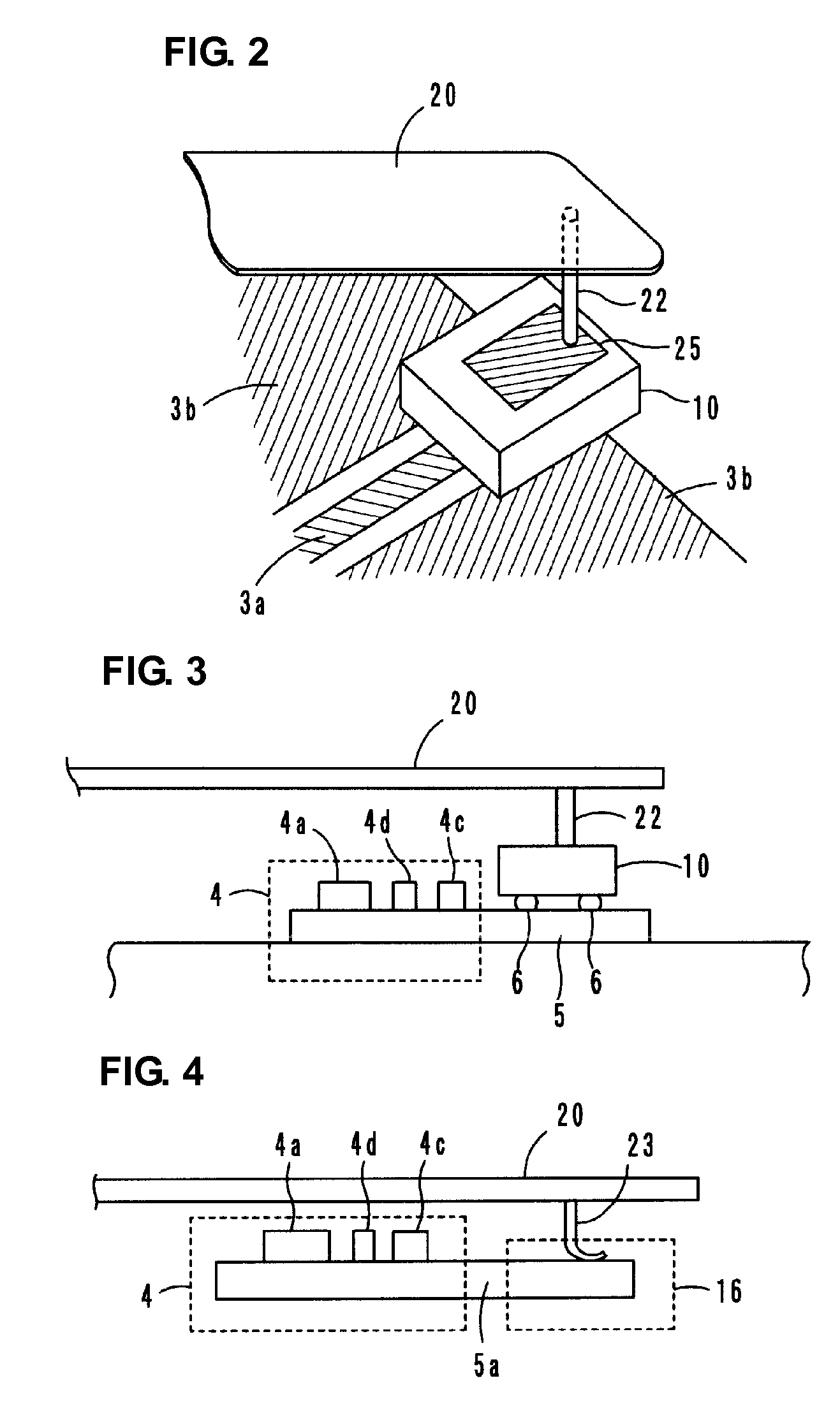
A product includes a power supply circuit board, which includes a power supply circuit having a stable frequency characteristic which enables communication among various products to be obtained. The product includes a power supply circuit board including a power supply circuit arranged thereon having an inductance element, and a wireless communication circuit board electrically connected to the power supply circuit. The wireless communication circuit board is mounted on the power supply circuit board. The product further includes a radiation plate which emits a transmission signal which is supplied from the power supply circuit through electromagnetic field coupling and which has a frequency substantially determined in accordance with a resonant frequency of the power supply circuit, and which is used to supply a reception signal to the power supply circuit through electromagnetic field coupling.

Description

BACKGROUND OF THE INVENTION[0001]1. Field of the Invention[0002]The present invention relates to products including power supply circuit boards, and particularly, relates to a product which includes a power supply circuit board having a power supply circuit electrically connected to a wireless communication circuit and which is used in an RFID (Radio Frequency Identification) system.[0003]2. Description of the Related Art[0004]In general, as a product management system, an RFID system includes a reader / writer which generates an induction field, and an IC tag (hereinafter referred to as a “wireless IC device”) which stores therein predetermined information regarding a product. This information is communicated between the reader / writer and the IC tag in a non-contact manner so that the information is transmitted. Examples of a wireless IC device used in an RFID system include devices disclosed in Japanese Unexamined Patent Application Publication No. 2005-136528 and Publication No. 20...

Claims


Application Information

Patent Timeline
Patent Type & Authority Applications(United States)
IPC IPC(8): H01F38/00H04B5/48
CPCG06K19/0701H01L2224/16225H01Q1/2208H01Q1/2216H01Q1/2283H01Q1/38H01Q7/00H01Q9/27H01Q11/08H05K1/0239H05K1/0243H05K1/16H05K1/162H05K1/165H05K2201/10098G06K19/0723G06K19/07G06K19/077H01Q1/24B42D25/305
Inventor KATO, NOBORUKIMURA, IKUHEI
Owner MURATA MFG CO LTD
Learn More