Power distribution on a vessel

a technology for power distribution and vessels, applied in the direction of emergency power supply arrangements, vessel construction, marine propulsion, etc., can solve the problems of large equipment of voluminous space and also a considerable amount of cables, and the conventional power distribution system may have some disadvantages and technical problems, and achieve the effect of reducing the requirements regarding the size of the cabling, cost-effective, and large cabling siz

Active Publication Date: 2017-12-28
SIEMENS ENERGY GLOBAL GMBH & CO KG +1
View PDF4 Cites 30 Cited by
  • Summary
  • Abstract
  • Description
  • Claims
  • Application Information

AI Technical Summary

Benefits of technology

[0010]The AC buses (the first AC bus and the second AC bus) may provide a one-phase or three-phase or even higher phase bus, in particular operating at a frequency between 50 Hz and 100 Hz. To operate the first DC bus at a first medium voltage and to operate the second DC bus at a second medium voltage may be advantageous in that it may reduce the size or cross-sectional size of the cable compared to the case when the DC buses would be operated at lower voltages. The inverter (for example the first inverter and the second inverter or also the below mentioned consumer inverter or battery inverter) may have the ability to convert a DC power stream to an AC power stream having adjustable frequency and / or vice versa.
[0043]Embodiments of the present invention may have the advantages to be compact, low cost, high redundancy. Further, battery backup may keep the vessel in position after blackout, thereby adding a further safety to the operation. Furthermore, seamless flow of power between systems may be provided, giving flexibility of configuration. Further, the generators may consume lower fuel. Further, soft start of the distribution system may be enabled. Further, a stable frequency on the grid may be achieved. The generators may require less maintenance and there may be a cleaner exhaust with less fumes due to more stable load condition (battery may work as a load shaver).

Problems solved by technology

However, conventional power distribution and systems may have some disadvantages and technical problems.
In particular, a large amount of equipment of voluminous space and also a considerable amount of cables may be required for the conventional systems.
Furthermore, generators need to have a considerable capacity.

Method used


Image

  • Power distribution on a vessel
  • Power distribution on a vessel
  • Power distribution on a vessel

Examples


Embodiment Construction

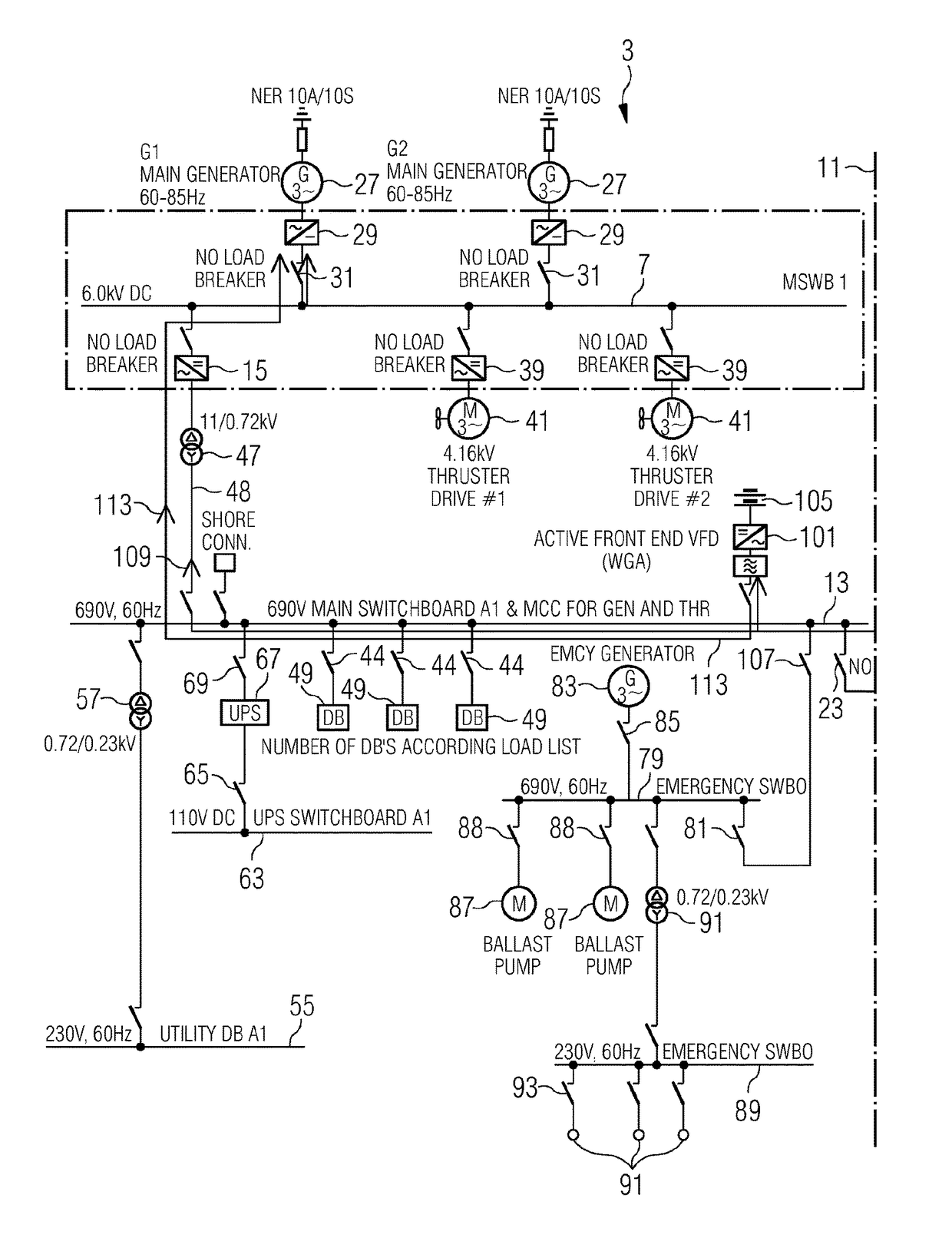
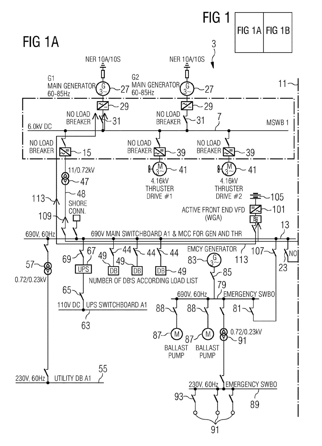
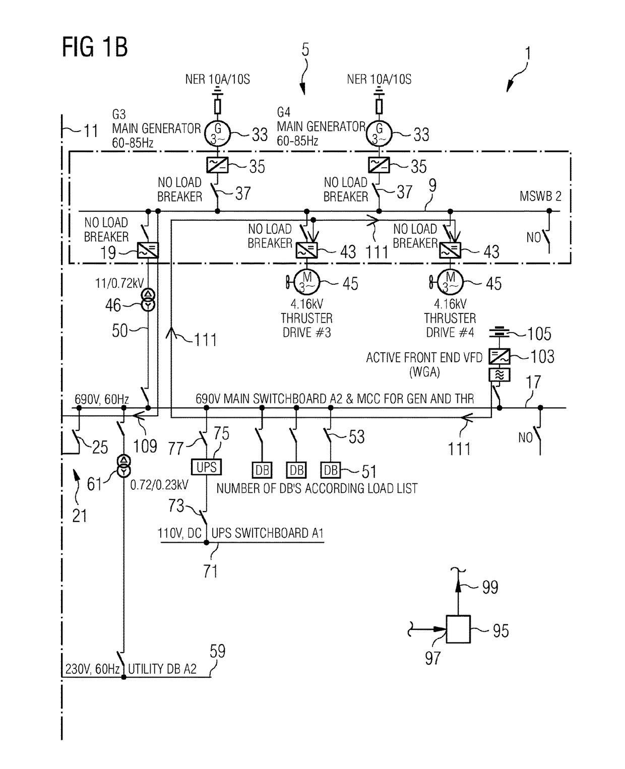
[0046]The schematic circuit diagram of the arrangement 1 for power distribution on a vessel illustrates a first system 3 and a second system 5 which share a number of features. The first system 3 comprises a first DC bus 7 which operates at a first medium voltage, in the illustrated example 6.0 kV DC. Similarly, the second system 5 comprises a second DC bus 9 which operates at a second medium voltage, for example between 5 kV and 10 kV DC. As is indicated in the FIGURE, the first DC bus 7 and the second DC bus 9 are separated by a barrier 11, they are independent from each other and / or are spaced apart from each other. Thus, there is no direct connection between the first DC bus 7 and the second DC bus 9.

[0047]The first system 3 further comprises a first AC bus 13 which operates at a low voltage, in the illustrated example 690 V, 60 Hz AC. A first inverter 15 is coupled between the first DC bus 7 and the first AC bus 13. The second system 5 comprises a second AC bus 17 which operate...


PUM


Abstract

An arrangement for power distribution on a vessel, having: a first DC bus operating at a first medium voltage; at least one second DC bus operating at a second medium voltage and having no direct connection with the first DC bus; a first AC bus operating at a low voltage; a first inverter coupled between the first DC bus and the first AC bus for allowing power flow from the first DC bus to the first AC bus in a first operation mode; a second AC bus operating at the low voltage; a second inverter coupled between the second DC bus and the second AC bus for allowing power flow from the second DC bus to the second AC bus in the first operation mode; a low voltage connection system for selectively connecting or disconnecting the first AC bus and the second AC bus.

Description

CROSS REFERENCE TO RELATED APPLICATIONS[0001]This application is the US National Stage of International Application No. PCT / EP2015 / 079340 filed Dec. 11, 2015, and claims the benefit thereof. The International Application claims the benefit of European Application No. EP15151256 filed Jan. 15, 2015. All of the applications are incorporated by reference herein in their entirety.FIELD OF INVENTION[0002]The present invention relates to an arrangement and to a method for power distribution on a vessel, in particular a ship or a platform.BACKGROUND OF INVENTION[0003]For operating a vessel, in particular a ship or a platform, e.g. oil exploration platform, electric energy needs to be distributed to a number of consumers. For example, thrusters and pumps need to be operated on a vessel. The different consumers require different voltage or may require AC power or DC power. In the state-of-the-art, medium voltage distribution systems which have traditional switch gears, transformers and VFDs ...

Claims


Application Information

Patent Timeline
Patent Type & Authority Applications(United States)
IPC IPC(8): H02J3/38B63H23/24H02J4/00
CPCH02J3/38H02J4/00B63H23/24H02J2310/42B63H21/17H02J9/062
Inventor GJERPE, PAUL FREDRIKHARTWIG, BERNDHILLER, MARCVOSS, WOLFGANG
Owner SIEMENS ENERGY GLOBAL GMBH & CO KG
Why Eureka
Try Eureka