Flowmeter

a flowmeter and flow rate technology, applied in the direction of fluid speed measurement, liquid/fluent solid measurement, instruments, etc., can solve the problems of inability to perform correct measurement, inability to perform measurement, etc., to achieve high resolution, reduce the amount of consumed power, and consume a small amount of power

Inactive Publication Date: 2005-01-06
PANASONIC CORP
View PDF6 Cites 29 Cited by
  • Summary
  • Abstract
  • Description
  • Claims
  • Application Information

AI Technical Summary

Benefits of technology

In order to solve the above problems, a flowmeter of the present invention includes: transmission / reception means provided in a flow path for performing transmission / reception using a state change of fluid; repetition means for repeating the transmission / reception; time measurement means for measuring a time or propagation repeated by the repetition means; flow rate detection means for detecting a flow rate based on a value of the time measurement means; and number-of-times change means for changing to a predetermined number of repetition times. The number of repetition times is changed to a number suitable for a variation such that an influence of a variation of a flow can be suppressed. As a result, reliable flow rate measurement with a high accuracy can be achieved.
The control section includes periodicity stabilizing means formed by a delay section capable of setting different delay times; and the control section changes an output timing of the driver circuit by switching the delay times. Since the measurement frequency is maintained to be constant by changing the delay time, the measurement frequency can be stabilized without giving an influence to driving of the ultrasonic wave transducers.

Problems solved by technology

Therefore, measurement over a long time period is necessary in order to obtain a reliable mean value, and hence such flow rate measurement cannot be performed within a very short space of time.
In the first to forth inventions, when any abnormality occurs, measurement either cannot be performed, or can be performed but with decreased accuracy.
The noise is counted as a measurement error, and accordingly, correct measurement cannot be performed.
Moreover, when the propagation time is varied due to a variation in temperature or the like, the phase at which noise is superposed is varied, and accordingly, a measurement error is varied.
As a result, a correction value cannot be stabilized.
Furthermore, since the measurement resolution is determined based on the resolution of the timer 54, simply averaging the measurement values cannot increase the accuracy of measurement.
When the operation clock of the timer 54 is increased so as to have a high frequency, various problems occur, i.e., an increase in current consumption, an increase in high-frequency noise, and an increase in size of circuitry.
Thus, a variation in the signal-reception detecting time, which is caused by superposition of reverberation of this vibration on the ultrasonic wave signal, cannot be decreased.

Method used


Image

  • Flowmeter
  • Flowmeter
  • Flowmeter

Examples


embodiment 1

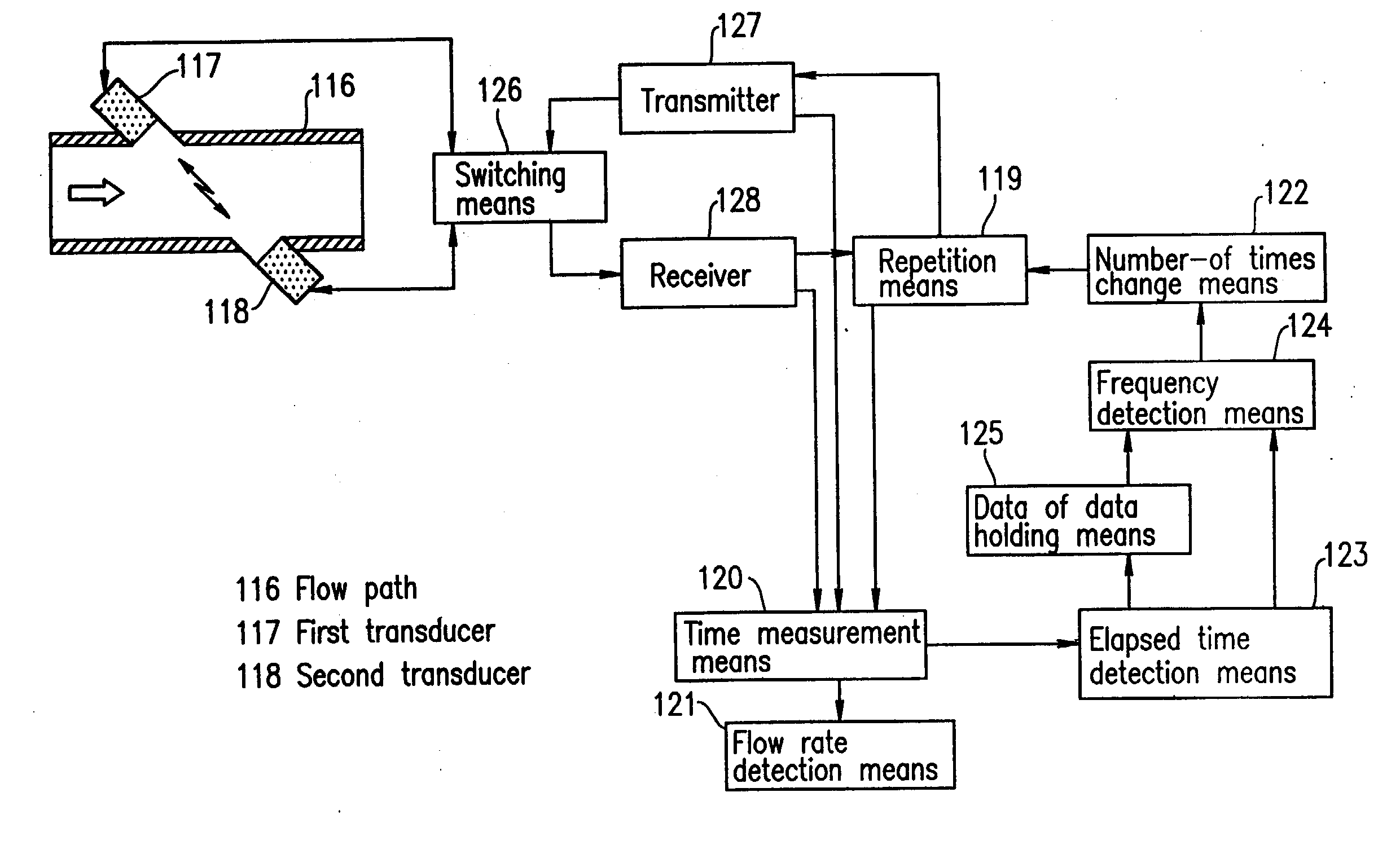
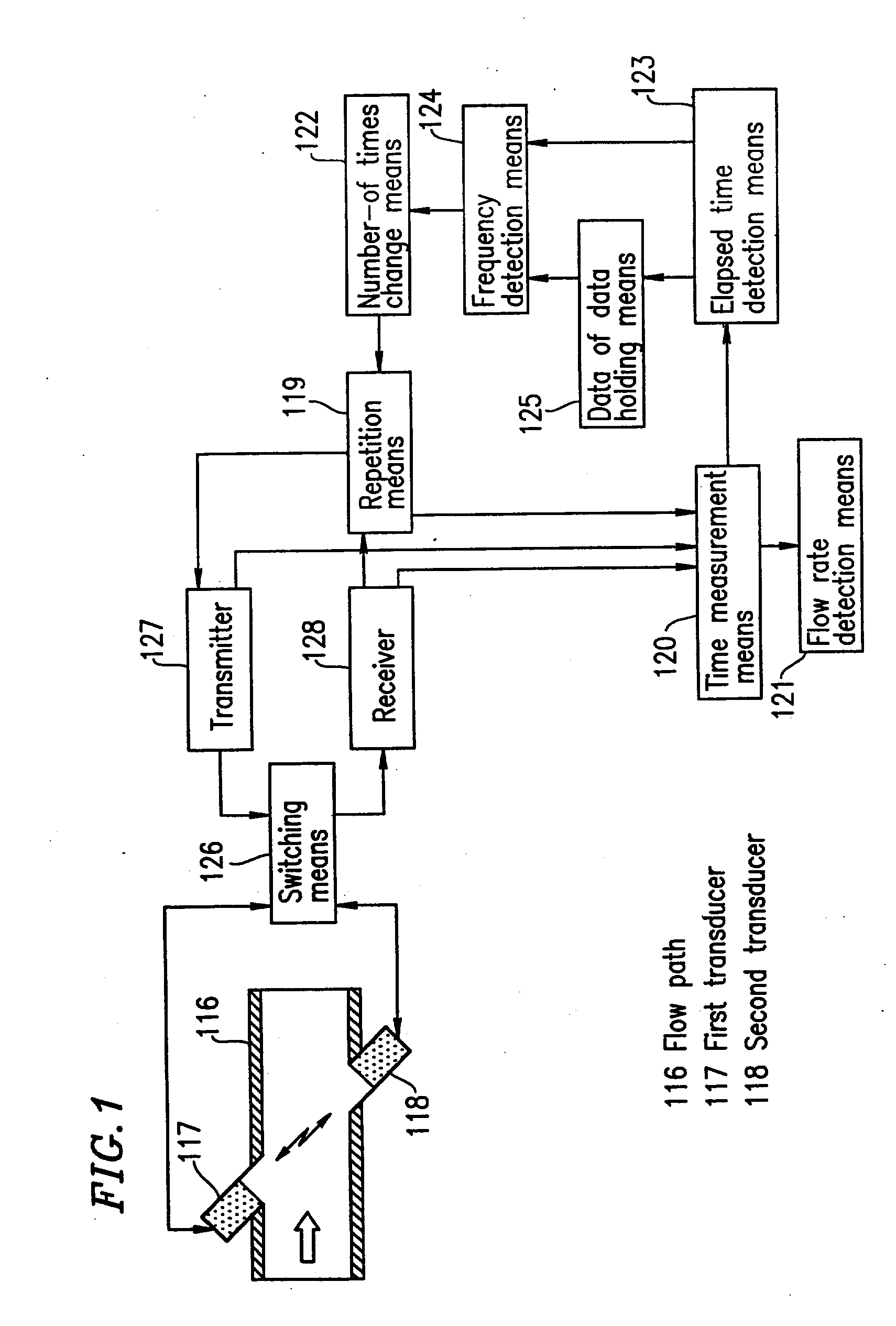
FIG. 1 is a block diagram showing a flowmeter according to embodiment 1 of the present invention. In FIG. 1, reference numeral 117 is first transmission / reception means which is provided in a flow path 116 and which functions as transmission / reception means for transmitting / receiving a signal by using propagation of a sonic wave as a state change in a fluid. Reference numeral 118 is second transmission / reception means as transmission / reception means. Reference numeral 119 is repetition means for repeating signal propagation between the first transmission / reception means 117 and the second transmission / reception means 118. Reference numeral 120 is time measurement means for measuring a propagation time of a sonic wave propagated during the repetition in the repetition means 119. Reference numeral 121 is flow rate detection means for detecting the flow rate based on a value from the time measurement means 120. Reference numeral 122 is number-of-times change means for successively maki...

embodiment 2

FIG. 6 is a flowchart showing an operation of a flowmeter according to embodiment 2 of the present invention. Embodiment 2 is different from embodiment 1 in that the process of embodiment 2 is structured such that the number of repetition times which is determined according to a frequency obtained by the frequency detection means is used in the next flow rate measurement. The structure of the flowmeter in embodiment 2 is the same as that shown in FIG. 1.

As shown in FIG. 6, measurement of propagation time T1 of an ultrasonic wave propagating from the first transducer is performed, while time measurement information Ci of the measurement means at that time is held in the data holding means. Measurement of propagation time T2 of an ultrasonic wave propagating from the second transducer is then performed, and the flow velocity and flow rate are calculated from times T1 and T2. Then, the frequency of a flow variation is detected from the held time measurement information Ci by using a ...

embodiment 3

FIG. 7 is a block diagram of a flowmeter according to embodiment 3 of the present invention. Embodiment 3 is different from embodiment 1 in that the flowmeter of embodiment 3 includes: flow rate variation identification means 129 to determine the magnitude of a flow rate variation detected by the flow rate detection means 121; and number-of-times change means 122 for changing the number of repetition times such that the flow rate variation identified by the flow rate variation identification means 129 is decreased, and that the flow rate variation identification means 129 operates using a standard deviation of the flow rate.

As shown in the flowchart of FIG. 8, the flow rate Qi is first measured. When the flow rate is equal to or higher than a predetermined value Qm (for example, 100 liter / hour), the number of repetition times is kept unchanged. When the flow rate is lower than a predetermined value Qm, standard deviation Hi is obtained based on n pieces of data before the measured...


PUM


Abstract

For the purpose of solving the above problems, the present invention includes: transmission / reception means provided in a flow path for performing transmission / reception using a state change of fluid; repetition means for repeating the transmission / reception; time measurement means for measuring a time of propagation repeated by the repetition means; flow rate detection means for detecting a flow rate based on a value of the time measurement means; and number-of-times change means for changing to a predetermined number of repetition times. With such a structure, an influence caused by a variation of a flow can be suppressed by changing the number of repetition times so as to be suitable for a variation. As a result, reliable flow rate measurement with a high accuracy can be achieved.

Description

FIELD OF INVENTION The present invention relates to a flowmeter for measuring the flow rate of liquid or air. The present invention relates to means for measuring a flow rate value in an accurate manner even when there is a variation in pressure or temperature. BACKGROUND OF INVENTION Conventionally, such a type of flowmeter is known, for example, in Japanese Laid-Open Publication No. 9-15006. As shown in FIG. 64, the flowmeter includes: a sampling program 2 for reading a measurement value, at an interval having a predetermined first sampling time, from an analog flow sensor 1 that measures the flow rate of gas; a consumed gas amount calculation program 3 for calculating the flow rate of consumed gas at a predetermined time; a mean value calculation program 4 for calculating the mean value of measurement values, which are read from the analog flow sensor at the first sampling time, at an interval of a second sampling time within a predetermined time period; a pressure variation fr...

Claims


Application Information

Patent Timeline
Patent Type & Authority Applications(United States)
IPC IPC(8): G01F1/66G01F1/72G01P5/24
CPCG01F1/66G01F1/667G01P5/247G01P5/245G01F1/72
Inventor UMEKAGE, YASUHIRONAGAOKA, YUKIOEGUCHI, OSAMUABE, SHUJINAKABAYASHI, YUJIOHJI, KENZOSHIBA, FUMIKAZUADACHI, AKIHISAHASHIMOTO, MASAHIKOSATO, TOSHIHARUFUJII, YUJI
Owner PANASONIC CORP
Why Eureka
Try Eureka