Miniaturized transmitter-receiver unit

Inactive Publication Date: 2006-05-16
ALPS ALPINE CO LTD
View PDF7 Cites 3 Cited by
  • Summary
  • Abstract
  • Description
  • Claims
  • Application Information

AI Technical Summary

Benefits of technology

[0011]In view of the circumstances of the related art, it is an object of the present invention to provide a miniaturized transmitter-recei

Problems solved by technology

Because the antenna substrate 26a is attached to the other side of the circuit substrate 28 using double-sided adhesive tape and power feeding to t

Method used


Image

  • Miniaturized transmitter-receiver unit
  • Miniaturized transmitter-receiver unit
  • Miniaturized transmitter-receiver unit

Examples


Embodiment Construction

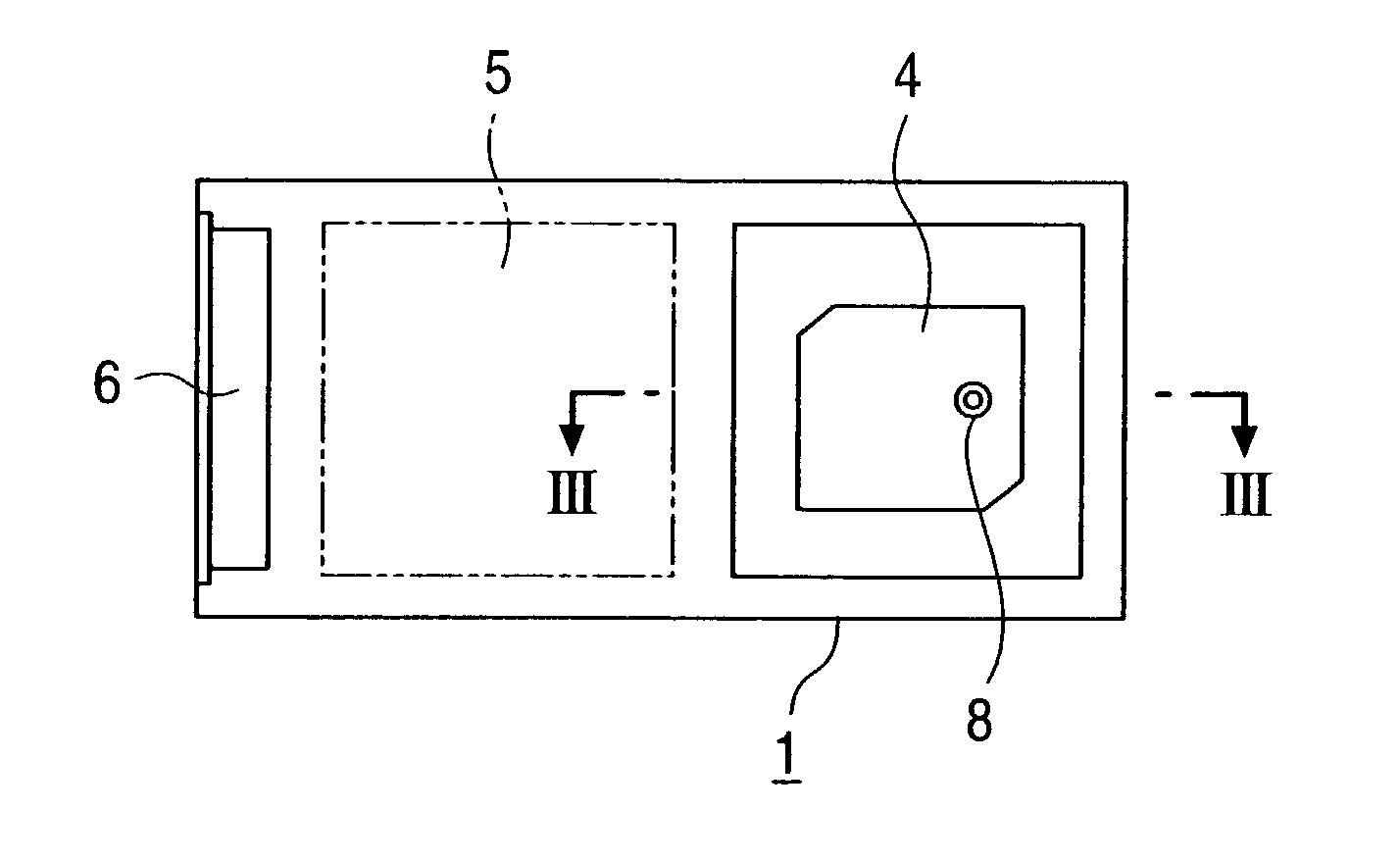
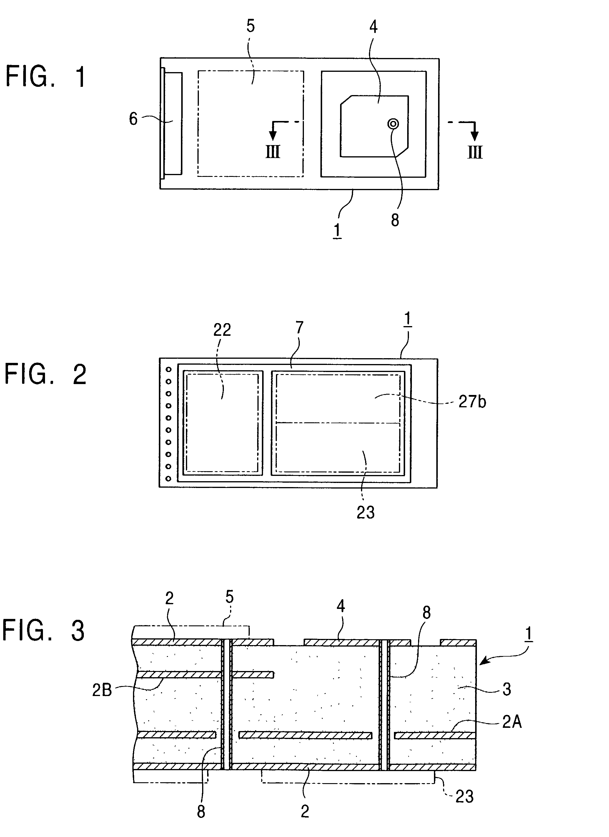
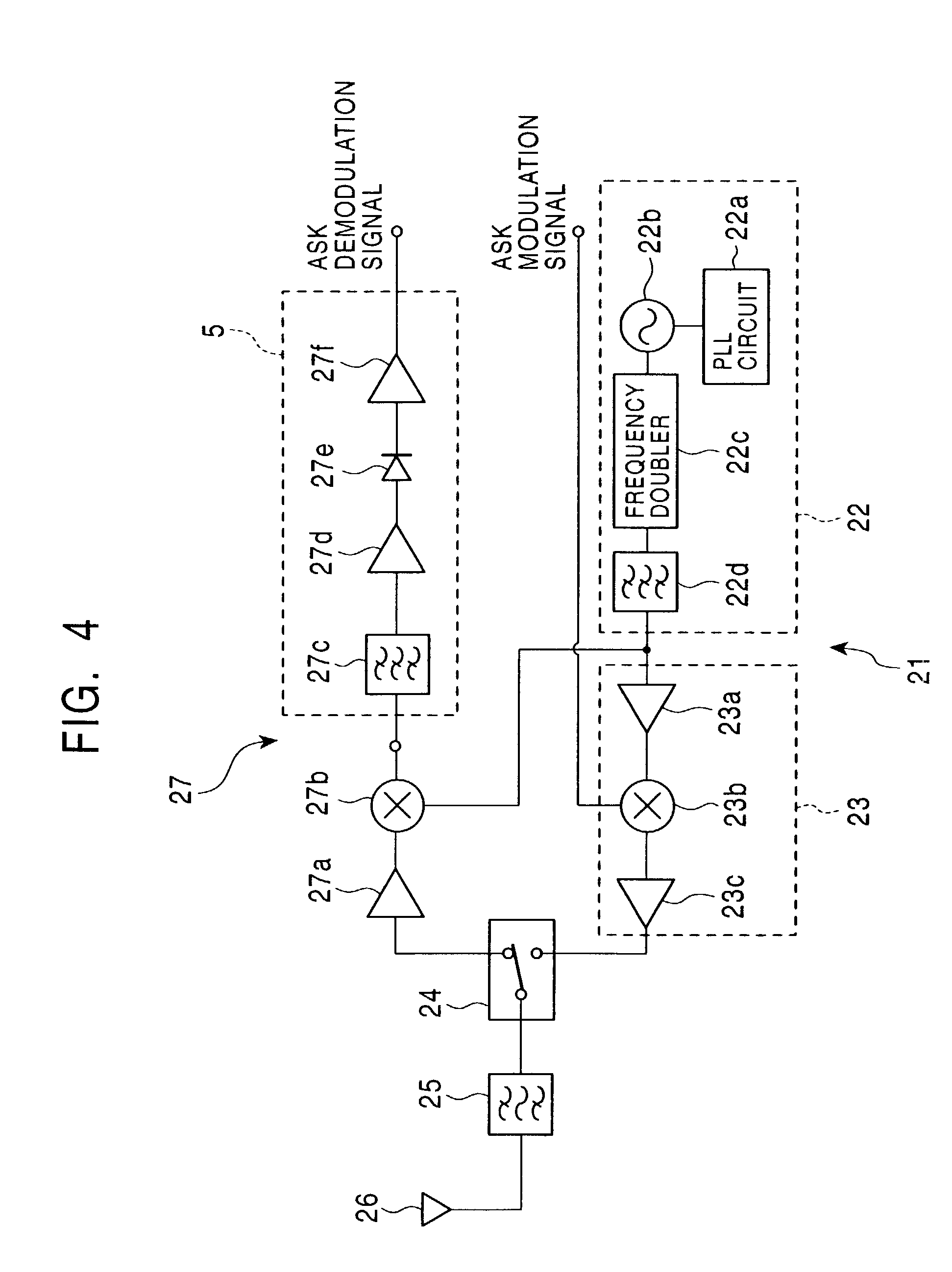
[0020]The present invention will become clear from the following description of the preferred embodiments with reference to the accompanying drawings. FIG. 1 shows the front side of a transmitter-receiver unit according to an embodiment of the present invention. FIG. 2 shows the rear side of the transmitter-receiver unit. FIG. 3 is an enlarged sectional view taken along the line III—III of FIG. 1.

[0021]Referring to FIGS. 1 to 3, a multilayer substrate 1, which is used as a circuit substrate, will now be described. The multilayer substrate 1 is formed by stacking a plurality of conductive patterns 2, which are formed of copper foil, and insulating layers 3 therebetween. As shown in FIG. 1, an antenna patch 4, an IF circuit 5, and a connector 6 are formed on one side of the multilayer substrate 1. The IF circuit 5 corresponds to components from a band pass filter 27c to a baseband amplifier 27f of a receiver circuit 27 of a transmitter-receiver circuit illustrated in FIG. 4. As descri...


PUM


Abstract

A transmitter-receiver unit has an antenna patch and an IF circuit, between which there is a large frequency difference, on a first side of a multilayer substrate. A high frequency circuit (including a local oscillator and a demodulation unit) except for the IF circuit is provided on a second side of the multilayer substrate. A ground conductive pattern is provided in the interior of the multilayer substrate. The circuit conductive pattern exposed at the second side of the multilayer substrate and a feeding point of the antenna patch conduct to each other through a through hole.

Description

[0001]This application claims the benefit of priority to Japanese Patent Application 2001-216998, filed on Jul. 17, 2001.BACKGROUND OF THE INVENTION[0002]1. Field of the Invention[0003]The present invention relates to transmitter-receiver units used in Electronic Toll Collection (ETC) systems.[0004]2. Description of the Related Art[0005]In ETC systems for toll roads such as turnpikes, with time-division two-way communication, transmission and reception is performed between an ETC transmitter-receiver terminal station installed at a toll booth and an ETC transmitter-receiver mounted in a vehicle using 5.8-GHz ASK modulated waves. Predetermined tolls can be collected by transmitting and receiving signals.[0006]FIG. 4 shows an example of a transmitter-receiver circuit used in these ETC systems. FIGS. 5A and 5B show the circuit layout of a transmitter-receiver unit with the transmitter-receiver circuit shown in FIG. 4. FIG. 5A illustrates the transmitter-receiver unit viewed from one si...

Claims


Application Information

Patent Timeline
IPC IPC(8): H04B1/44G07B15/00H01Q13/08H01Q23/00H04B1/38H04B1/3822H05K1/16
CPCH04B1/408H05K1/16H04B1/40
Inventor ITO, SHIGEHIROSAITO, YOSHIO
Owner ALPS ALPINE CO LTD
Why Eureka
Try Eureka