Hybrid multi-antenna system and wireless communication apparatus using the same

a multi-antenna system and wireless communication technology, applied in the field of hybrid multi-antenna systems and wireless communication apparatuses using the same, can solve the problems of large overall dimension of multi-antenna systems, co-channel interference for antenna reception, and inability to adapt to multi-antenna communication systems with multiple input multiple output (mimo) technology, etc., to achieve simple antenna structure, low cost, and small size

Active Publication Date: 2014-10-07
LITE ON ELECTRONICS (GUANGZHOU) LTD +1
View PDF9 Cites 5 Cited by
  • Summary
  • Abstract
  • Description
  • Claims
  • Application Information

AI Technical Summary

Benefits of technology

[0012]To sum up, the hybrid multi-antenna system provided by an exemplary embodiment of the present disclosure has the simple antenna structure, the small size, and the low cost. Furthermore, the hybrid multi-antenna system is easy to be implemented, integrated and embedded in the wireless communication apparatus.

Problems solved by technology

Therefore, owing to its large dimension, the dual-polarized antenna is not suitable for the multiple-input multiple-output (MIMO) multi-antenna communication system.
However, due to that the antennas are arranged compactly, the signals received or transmitted by the antennas are mutual coupled when each of the antennas operates in the same or similar band, such that it has the problem of the co-channel interference for the antenna reception.
However, since the distances between the antennas in the multi-antenna system are limited, the overall dimension of the multi-antenna system is very large, and is unable to be integrated in the thin, light, and small wireless communication apparatus.
Since the strobe feed-in manner is usually used in the patch antenna or microstrip antenna, the location of the feed-in end of the antenna must match the location of the radio signal output end on the system circuit board, and this means that the other antenna is unable to match the same system circuit board.

Method used


Image

  • Hybrid multi-antenna system and wireless communication apparatus using the same
  • Hybrid multi-antenna system and wireless communication apparatus using the same
  • Hybrid multi-antenna system and wireless communication apparatus using the same

Examples


Embodiment Construction

[0023][Exemplary Embodiment of Hybrid Multi-Antenna System]

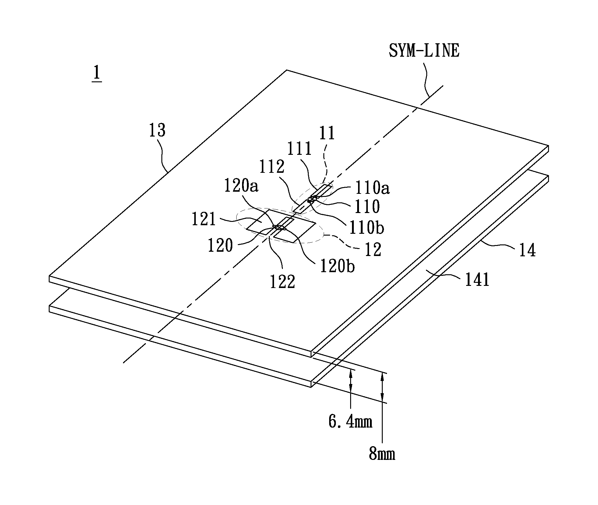
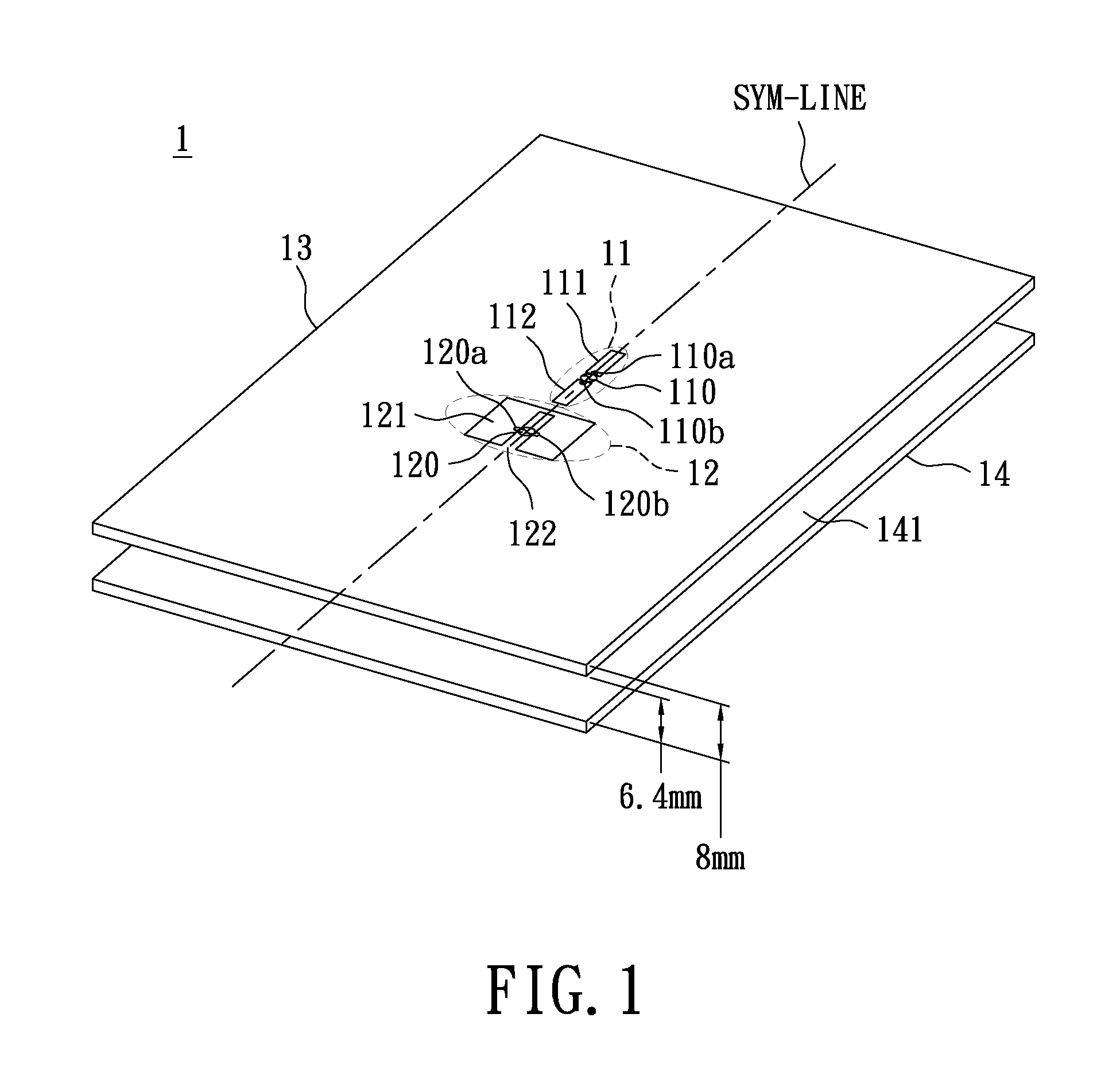
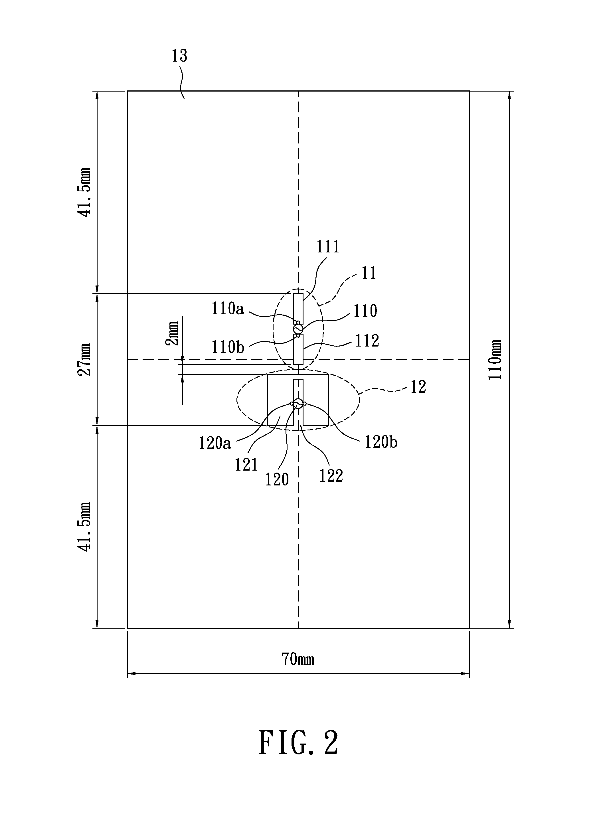
[0024]Referring to FIG. 1, FIG. 1 is a schematic diagram showing a three-dimensional structure of a hybrid multi-antenna system according to an exemplary embodiment of the present disclosure. The hybrid multi-antenna system 1 comprises a dipole antenna 11, a monopole-slot antenna 12, an antenna substrate 13, and a system circuit board 14. The system circuit board 14 has a system ground plate 141, and the system ground plate 141 is a conductive material. The antenna substrate 13 is located on the system circuit board 14. The system ground plate 141 is served as a reflector of the hybrid multi-antenna system 1. Since the system ground plate 141 is the reflector of the hybrid multi-antenna system, the area of the system ground plate 141 must cover the overall vertical projected area of the dipole antenna 11 and the monopole-slot antenna 12. The dipole antenna 11 and the monopole-slot antenna 12 may be printed on antenna substra...


PUM


Abstract

A hybrid multi-antenna system includes a system circuit board, an antenna substrate, at least a dipole antenna, and at least a monopole-slot antenna. The system board has at least a system ground plate, and the system ground plate is served as a reflector of the hybrid multi-antenna system. The antenna substrate and the system ground plate have a first distance therebetween. The dipole antenna having a first signal feed-in source and the monopole-slot antenna having a second signal feed-in source respectively provide a first and second operating band, and they are on a surface of the antenna substrate. The monopole-slot antenna is located nearby the dipole antenna. The monopole-slot antenna and the dipole antenna have a second distance therebetween. The first and second signal feed-in sources are vertical to each other, and have the phase difference of 90°.

Description

BACKGROUND[0001]1. Technical Field[0002]The present disclosure relates to an antenna, in particular, to a hybrid multi-antenna system and a wireless communication apparatus using the same.[0003]2. Description of Related Art[0004]Now, the communication technology develops rapidly and maturely, and thus people usually use the wireless communication apparatuses to surf the internet and communicate by telephone. Regardless of kinds of wireless communication apparatuses, the wireless communication apparatuses need antennas to receive and transmit the wireless signals at specific frequencies. For example, the indoor and outdoor access points (AP) having antennas are the bridges of the wireless communication apparatuses.[0005]In general, the patch antennas or microstrip antennas have been widely used in outdoor AP due to their characteristics of high directivity and antenna gain.[0006]Some related publications have disclosed the dual-polarized antenna array having a feed-in network and mul...

Claims


Application Information

Patent Timeline
Patent Type & Authority Patents(United States)
IPC IPC(8): H01Q21/00H01Q9/28H01Q13/10H01Q21/30
CPCH01Q13/10H01Q21/30H01Q9/285
Inventor LEE, CHENG-TSESU, SAOU-WEN
Owner LITE ON ELECTRONICS (GUANGZHOU) LTD
Why Eureka
Try Eureka