Minkowski-based microstrip patch antenna and manufacturing method thereof

A microstrip patch antenna and microstrip patch technology, which are applied in the field of wireless communication, can solve the problems of antenna size limitation, large antenna size, and difficulty in conformality, and achieve the effect of overcoming large size, easy integration, and easy conformality.

Inactive Publication Date: 2017-06-23
荣瓴智能科技(苏州)有限公司
View PDF3 Cites 7 Cited by
  • Summary
  • Abstract
  • Description
  • Claims
  • Application Information

AI Technical Summary

Problems solved by technology

[0004] Traditional square microstrip patch antennas usually resonate at half a wavelength, and the size of the antenna is strictly limited
In the specific application process, the trad

Method used


Image

  • Minkowski-based microstrip patch antenna and manufacturing method thereof
  • Minkowski-based microstrip patch antenna and manufacturing method thereof
  • Minkowski-based microstrip patch antenna and manufacturing method thereof

Examples


Embodiment Construction

[0028] The present invention will be further described below in conjunction with drawings and embodiments.

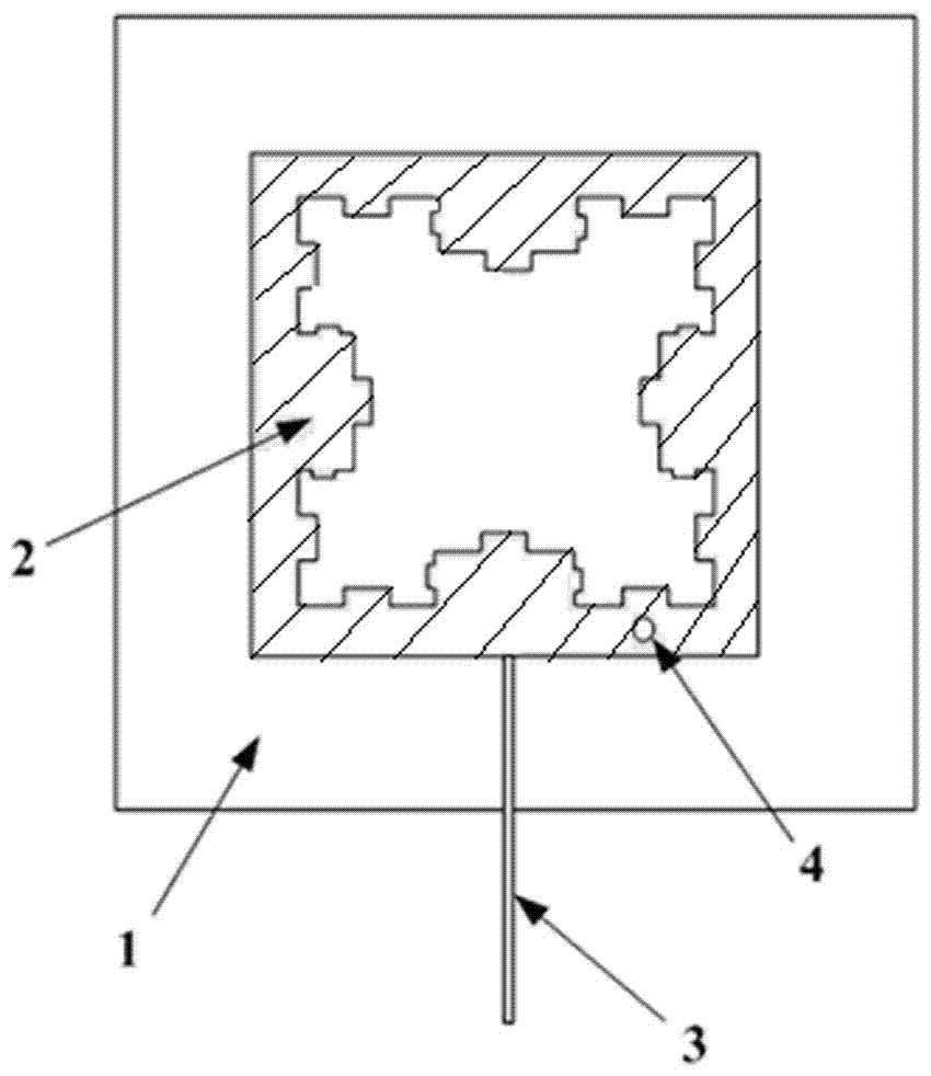
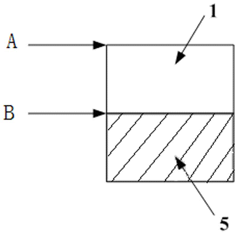
[0029] like figure 1 , 2 As shown, a microstrip patch based on the secondary Minkowski fractal structure is composed of a dielectric plate 1, a radiation unit 2, a feed unit 3, a ground via 4 and a ground unit 5, and the dielectric plate has a first surface A and the second surface B corresponding thereto; the radiation unit 2 is arranged on the first surface A of the dielectric board 1; the feed unit 3 is connected to the radiation unit 2 and is also arranged on the first surface A of the dielectric board 1 Above; the ground via hole 4 passes through the radiation unit 2 and the dielectric board 1 when punching, so that the radiation unit 2 communicates with the ground unit 5 to form a short circuit; the ground unit 5 is arranged on the second surface B of the dielectric board 1, and The dielectric plate 1 may not be completely covered. However, the high-frequency e...


PUM

PropertyMeasurementUnit
Widthaaaaaaaaaa
Widthaaaaaaaaaa
Return lossaaaaaaaaaa

Abstract

The invention relates to a Minkowski-based microstrip patch antenna and a manufacturing method thereof. Various kinds of technical and shaping operations are performed on a microstrip patch antenna; on the basis of a Minkowski split structure, slotting treatment is performed according to the one-dimensional characteristics of a microstrip patch, and a short-circuit loading technique is utilized, and therefore, the Minkowski split structure-based microstrip patch antenna can be obtained. The operating frequency of the antenna is 915 MHz; and the size of the patch can be as small as 24.6 mm*24.6 mm, the height of the patch is only 1.2 mm, and therefore, the size of the antenna can be greatly decreased. The antenna has the advantages of simple structure, small size, light weight, low profile and easiness in integration, and can be used for an ultra-high frequency (UHF) RFID (radio frequency identification) system; and the patch antenna is easy to manufacture, and therefore, practical requirements for being applied to anti-metal environments, of the antenna can be satisfied.

Description

technical field [0001] The invention belongs to the field of wireless communication, and in particular relates to a Minkowski-based microstrip patch antenna and a manufacturing method thereof. Background technique [0002] Radio Frequency Identification (RFID) technology can be traced back to the radio frequency identification system proposed by the British Air Force during World War II. During the Battle of Britain, the fighter planes of the British and German air forces were very similar in appearance, and they could not be accurately identified with the naked eye during high-speed flight. The British Air Force has installed a response device on its own fighter plane, which transmits the pre-programmed pulse code through the interrogation device on the ground. If it is its own fighter plane, the response device on the fighter plane will send the agreed pulse code Reflected to the land station; if the fighter emits a wrong code or does not respond, it is judged as an enemy...

Claims


Application Information

Patent Timeline
IPC IPC(8): H01Q1/38H01Q1/50H01Q1/48
CPCH01Q1/38H01Q1/48H01Q1/50
Inventor 何怡刚周婷婷张楠史露强罗旗舞李兵刘慧
Owner 荣瓴智能科技(苏州)有限公司
Why Eureka
Try Eureka