
Antenna mounting device and base station antenna system

a technology of mounting device and antenna system, which is applied in the direction of antennas, antenna details, electrical apparatus, etc., can solve the problems of high cost of adjustment of mechanical tilt angle of base station antenna, unfavorable resistance to external disturbance loads such as strong wind, and achieve high stability against external disturbance loads. , the effect of easy adjustment of mechanical tilt angl

Active Publication Date: 2021-11-25
COMMSCOPE TECH LLC
View PDF4 Cites 5 Cited by
  • Summary
  • Abstract
  • Description
  • Claims
  • Application Information

AI Technical Summary

Benefits of technology

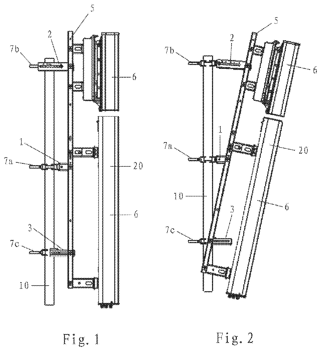
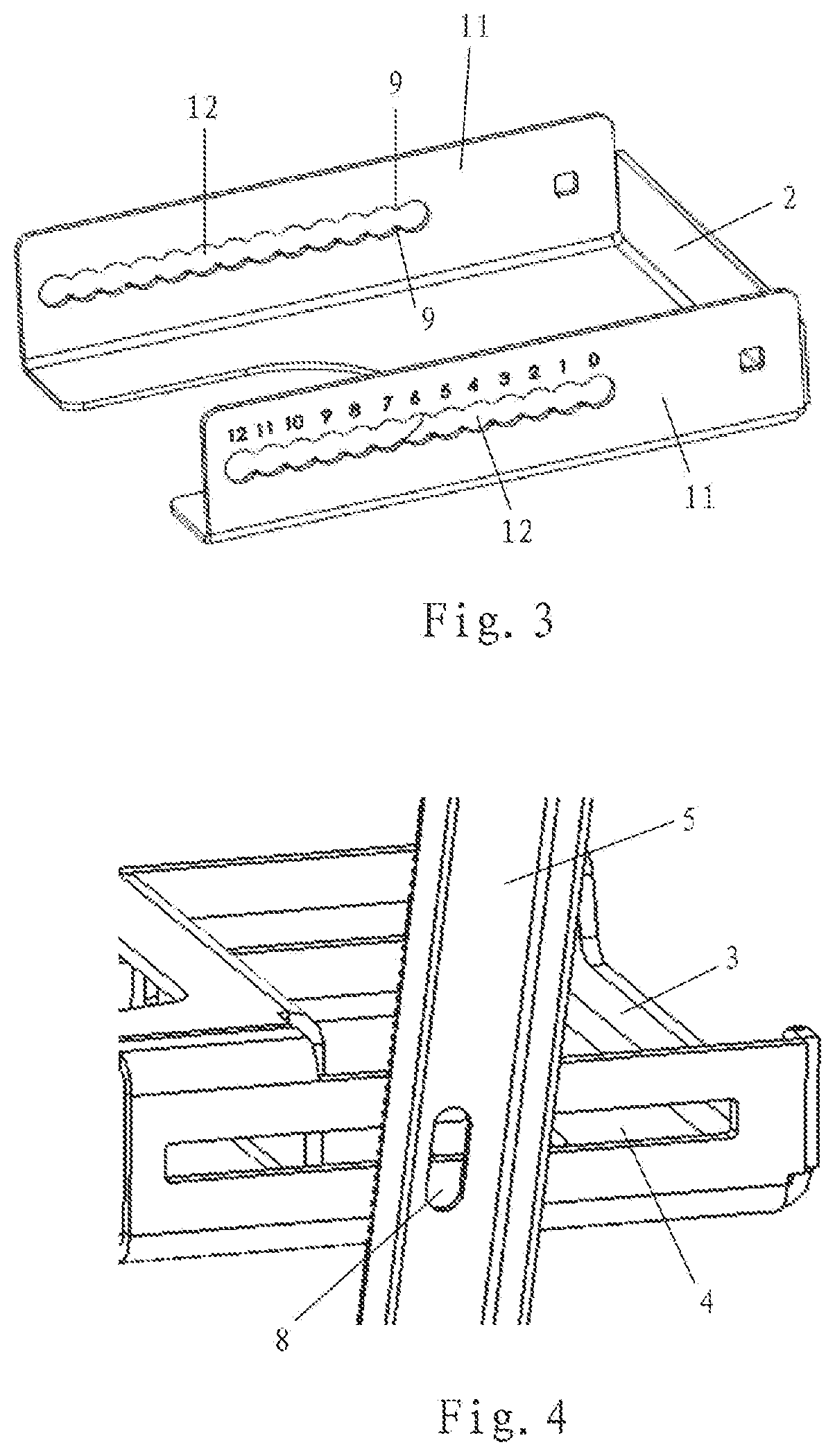
The present disclosure provides an antenna mounting device with a simple structure that enables easy adjustment of the mechanical tilt angle of the base station antenna arrangement with stability in place. This reduces the maintenance load of the base station antenna arrangement and improves its service life. Compared to prior art adjustment devices, the structure of the adjustment arm is simpler and its size is more compact. The middle region of the base station antenna arrangement refers to a region symmetrical from the center point of its longitudinal extension. The adjustment arm may have an elongated hole with protrusions distributed in at least one of its longitudinal sides, which divide the elongated hole into the plurality of connection positions. The protrusions may be uniformly distributed.

Problems solved by technology

In particular, when the V-shaped structure is almost closed, its resistance to external disturbance loads such as strong wind is unfavorable.
In addition, due to the force from the weight of the base station antenna, the adjustment of the mechanical tilt angle of the base station antenna is costly.

Method used


Image

  • Antenna mounting device and base station antenna system
  • Antenna mounting device and base station antenna system
  • Antenna mounting device and base station antenna system

Examples


Embodiment Construction

[0037]The present disclosure will be described below with reference to the attached drawings, which show the embodiments of the present disclosure. However, it should be understood that the present disclosure can be presented in many different ways and is not limited to the specific embodiments described below. In fact, the specific embodiments described below are intended to make the disclosure of the present disclosure more complete, so that those of ordinary skill in the art can fully understand the protection scope of the present disclosure. It should also be understood that the embodiments disclosed in the present disclosure may be combined in various ways to provide more additional embodiments.

[0038]It should be understood that the terms used in the Specification are only used to describe specific embodiments and are not intended to limit the present disclosure. Unless otherwise defined, all terms used in the Specification, including technical terms and scientific terms, have ...


PUM


Abstract

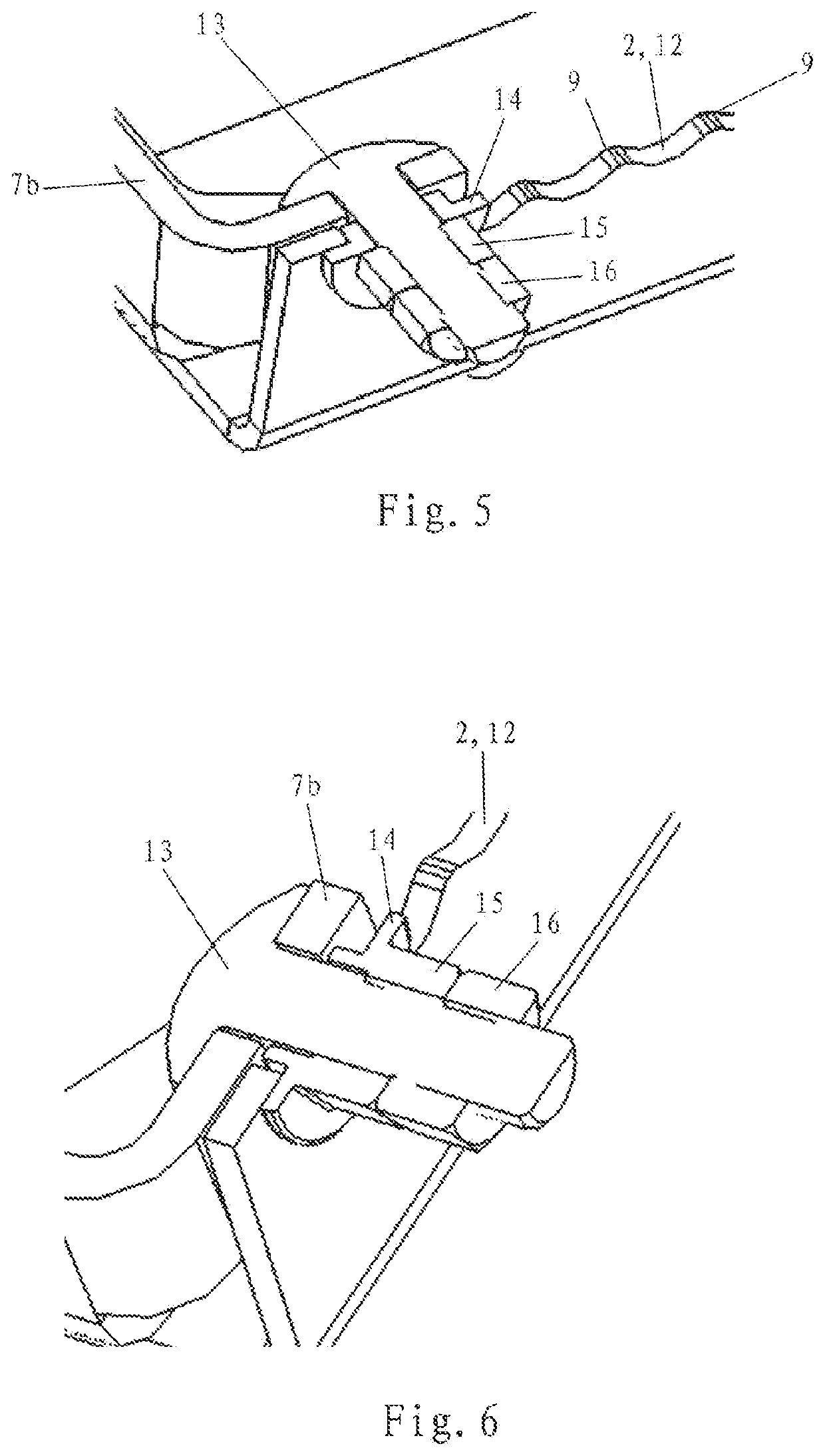
The present disclosure relates to an antenna mounting device and a base station antenna system. The antenna mounting device includes a hinge device and an adjustment arm. The hinge device is configured to be mounted to a pole by a clamp and configured to pivotally connect a base station antenna arrangement. The adjustment arm is configured to be mounted to the pole by a clamp and configured to connect the base station antenna arrangement. The connection of the hinge device with the base station antenna arrangement is located in a middle region of a longitudinal extension of the base station antenna arrangement [having a longitudinal extension] of a maximum of ⅓ of the longitudinal extension of the base station antenna arrangement. A connection of the adjustment arm with the base station antenna arrangement is located in one of two end regions of the base station antenna arrangement. The adjustment arm has a plurality of connection positions for the corresponding clamp, which are configured to define a plurality of different mechanical tilt angles of the base station antenna arrangement about the hinge device. The antenna mounting device realizes easy adjustment of the mechanical tilt angle and good resistance against external disturbance loads.

Description

RELATED APPLICATION[0001]The present application claims priority from and the benefit of Chinese Utility Model Application No. 202020868312.5, filed May 21, 2020, the disclosure of which is hereby incorporated herein in its entirety.FIELD OF THE INVENTION[0002]The present disclosure generally relates to the field of wireless communication. In particular, the present disclosure relates to an antenna mounting device and a base station antenna system including such an antenna mounting device.BACKGROUND OF THE INVENTION[0003]In a wireless communication system, signal transmission and reception are realized by base station antennas. The position of the base station antenna is important for the wireless communication network, which will affect the coverage of the base station antenna. Therefore, in the process of installing and using the base station antenna, the position of the base station antenna may need to be adjusted accordingly, so that the coverage area of the base station antenna...

Claims


Application Information

Patent Timeline
Patent Type & Authority Applications(United States)
IPC IPC(8): H01Q1/12H01Q1/24
CPCH01Q1/125H01Q1/246H01Q1/1264
Inventor WANG, ZHIGANGTANG, PULIANGSU, RUIXINLIU, MAOSHENGLIU, NENGBIN
Owner COMMSCOPE TECH LLC
Learn More