Air conditioner

An air-conditioning device, air-conditioning technology, applied in air-conditioning systems, space heating and ventilation, space heating and ventilation details, etc., can solve problems such as rising maintenance costs and heavy maintenance burdens

Inactive Publication Date: 2005-09-21
DAIKIN IND LTD
View PDF1 Cites 5 Cited by
  • Summary
  • Abstract
  • Description
  • Claims
  • Application Information

AI Technical Summary

Problems solved by technology

However, for a device that must be cleaned regularly, the maintenance burden is large, which may lead to an increase in maintenance costs

Method used


Image

  • Air conditioner
  • Air conditioner
  • Air conditioner

Examples


Embodiment 1

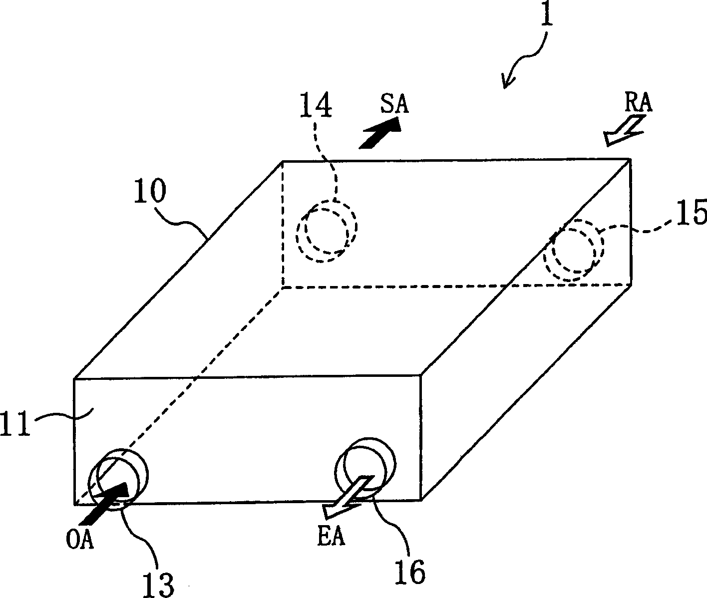
[0172] The humidity control device of Example 1 is composed of the air conditioner of the present invention, and dehumidifies and ventilates the room. Such as figure 1 As shown, the humidity control device 1 of Embodiment 1 is provided with a substantially flat cubic housing 10, a suction port 13 for sucking in outdoor air, a blower port 14 for blowing air indoors, a suction port 15 for sucking indoor air, and a blown-out port for outdoor air. Air outlet 16.

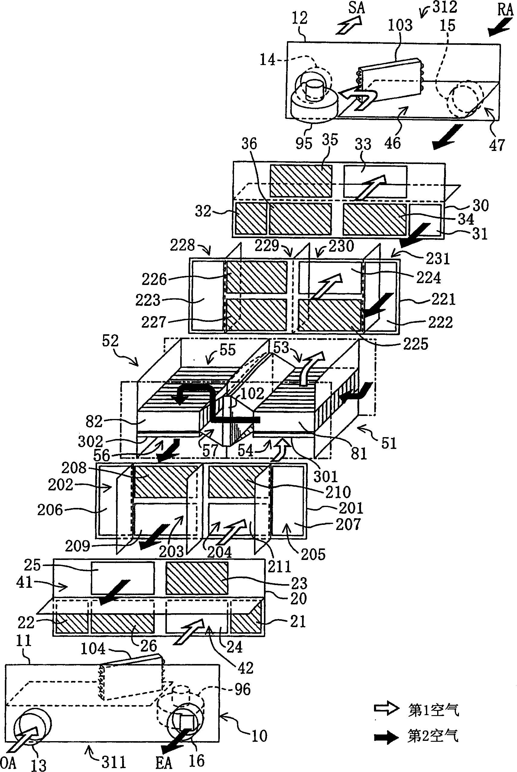
[0173] Such as figure 2 As shown, a first adsorption element 81 and a second adsorption element 82 are accommodated in the housing 10 . The first adsorption element 81 and the second adsorption element 82 constitute air-conditioning elements, respectively. In addition, a refresh heat exchanger 102 , a first heat exchanger 103 , and a second heat exchanger 104 are provided in the casing 10 . These heat exchangers 102 , 103 , and 104 are provided in a refrigerant circuit (not shown), and the refrigerant circulates in...

Deformed example 1-

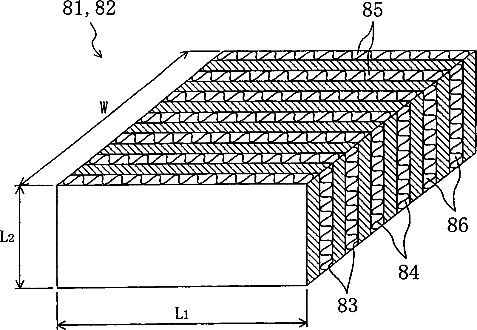
[0232] In the above-mentioned embodiment, the refreshment heat exchanger 102 is installed in an upright state between the first adsorption element 81 and the second adsorption element 82 , however, the installation state of the refreshment heat exchanger 102 is not particularly limited. For example Figure 5A and Figure 5B As shown, the renewing heat exchanger 102 may also be arranged laterally, so that the air flow direction during heat exchange becomes the up-down direction.

Deformed example 2-

[0234] In the above-mentioned embodiment, the air heated by the renewal heat exchanger 102 is immediately introduced into the humidity-conditioning side passage 85 of the adsorption elements 81, 82, however, it can also be used as Figure 6A and Figure 6B As shown, the air heated by the regeneration heat exchanger 102 is once introduced into the cooling-side passage 86 of the adsorption elements 81 and 82 , and then introduced into the humidity-conditioning-side passage 85 . Accordingly, it is possible to more efficiently heat the adsorption elements 81 and 82 to be renewed, and improve the renewal efficiency.


PUM


Abstract

A humidity control device includes a first adsorption element (81) and a second adsorption element (82). A first filter (301) is provided under the first adsorption element (81), while a second filter (302) is provided under the second adsorption element (82). The humidity control device performs first operation and second operation alternately. Directions of air flowing through the respective filters (301, 302) are reversed between the first operation and the second operation. Reversal of the direction of the air flowing through each filter (301, 302) removes dust and the like from each filter (301, 302).

Description

technical field [0001] The present invention relates to an air conditioner that supplies treated air to a room or the like. Background technique [0002] Conventionally, a ventilator including a so-called total heat exchanger 503 has been known as a type of air-conditioning apparatus. Such as Figure 39 As shown, the ventilator includes an air supply passage 501 for supplying outdoor air to a room, and an exhaust passage 502 for discharging indoor air to the outside. "OA" in the figure indicates outdoor air, "SA" indicates air supplied indoors (supply air), "RA" indicates indoor air, and "EA" indicates air discharged outdoors (exhaust air). [0003] The total heat exchanger 503 has a first flow path 504 and a second flow path 505 . The first flow path 504 is provided in the air supply passage 501 , and the second flow passage 505 is provided in the exhaust passage 502 . On the upstream side of the first flow path 504 and the second flow path 505 , filters 506 and 507 for ...

Claims


Application Information

Patent Timeline
Patent Type & Authority Applications(China)
IPC IPC(8): B01D53/26F24F3/14
CPCF24F2011/0002F24F3/1411F24F3/1429B01D53/261F24F3/147F24F3/16F24F13/28F24F7/08F24F8/10
Inventor 薮知宏成川嘉则石田智
Owner DAIKIN IND LTD
Why Eureka
Try Eureka