High-frequency heat treatment coil, outer-side joint member for constant-velocity universal joint, and constant-velocity universal joint

a technology of constant-velocity universal joints and heat treatment coils, which is applied in the direction of heat treatment apparatus, furnaces, magnetic bodies, etc., can solve the problems of coil damage, and achieve the effect of high accuracy, suppressing the influence of deformation and distortion involved in brazing, and skilled brazing technology

Active Publication Date: 2014-09-04
NTN CORP
View PDF6 Cites 3 Cited by
  • Summary
  • Abstract
  • Description
  • Claims
  • Application Information

AI Technical Summary

Benefits of technology

[0039]In the first high-frequency heat treatment coil of the present invention, the influence of deformation and distortion involved in brazing can be suppressed. Therefore, the assembled coil can keep high accuracy, and a skilled brazing technology is not required. Further, a coil can be assembled in a short period of time, and achieves excellent productivity and low cost. Thus, the first high-frequency heat treatment coil of the present invention is a coil with high accuracy; hence a gap between a heating section which greatly influences heat treatment quality and a portion to be heated can be kept to be a predetermined dimension stably, and high-quality heat treatment can be performed.
[0040]In the case where a coil body in which a current passage through which a high-frequency current flows is formed is formed by machining in an integral manner, a self-heating amount can be reduced, and cracking and the like caused by a self-heating amount can be prevented effectively, with the result that long life of the coil can be achieved. Further, the number of components can be reduced as a whole, and the assembly performance can be enhanced.
[0041]By setting a current flowing through a joining section between the cover member and the coil body to be a minute current and providing the joining section at a position which does not contribute to heating, a current har

Problems solved by technology

However, the coil may be damaged by a stress generated by repeating self-heatin

Method used


Image

  • High-frequency heat treatment coil, outer-side joint member for constant-velocity universal joint, and constant-velocity universal joint
  • High-frequency heat treatment coil, outer-side joint member for constant-velocity universal joint, and constant-velocity universal joint
  • High-frequency heat treatment coil, outer-side joint member for constant-velocity universal joint, and constant-velocity universal joint

Examples


Embodiment Construction

[0070]Now, embodiments of the present invention are described with reference to the drawings.

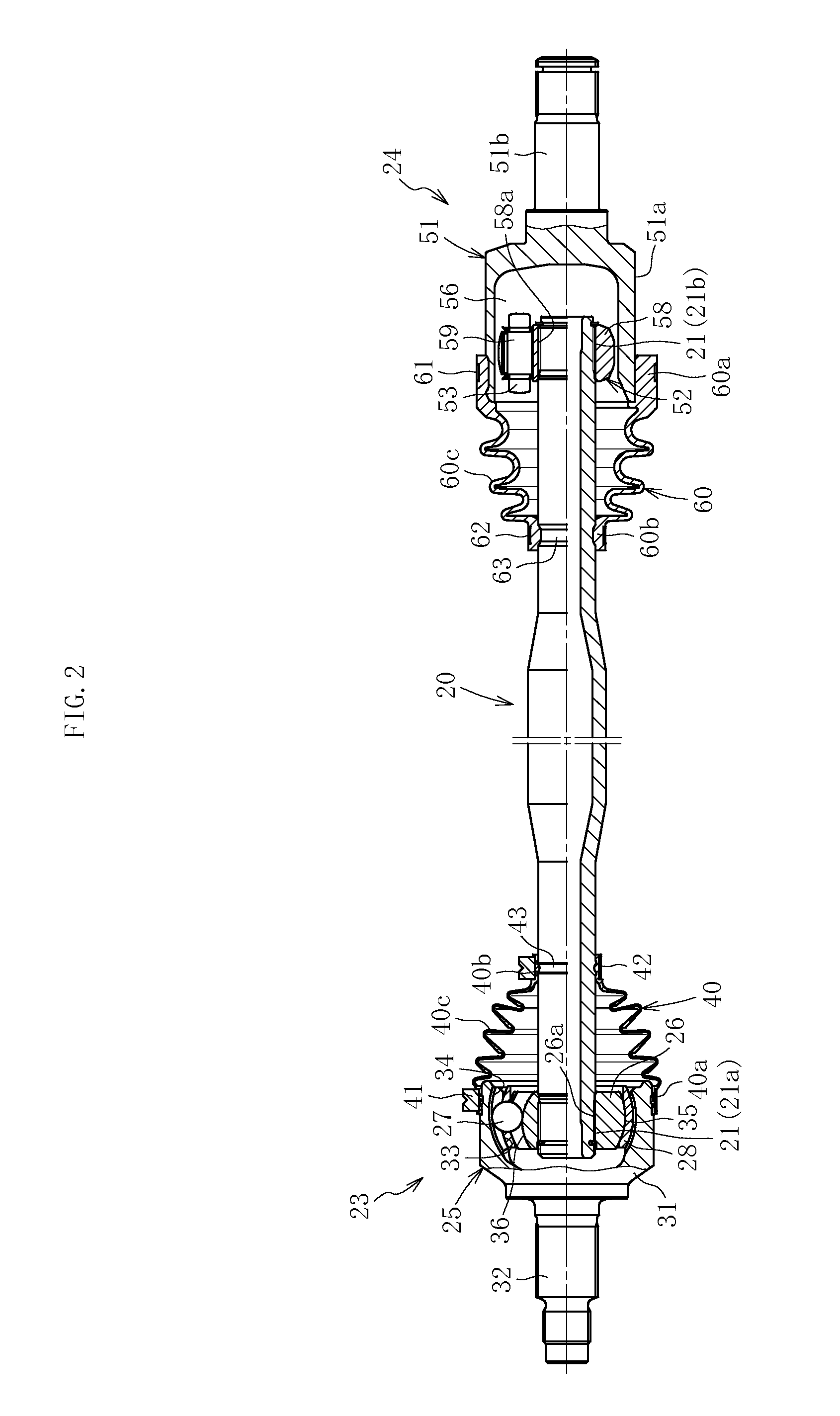
[0071]FIG. 2 illustrates a drive shaft of the present invention, and the shaft comprises a hollow shaft 20, a fixed type constant velocity universal joint 23 connected to one end portion of the shaft 20, and a plunging type constant velocity universal joint 24 connected to the other end portion of the shaft 20.

[0072]The fixed type constant velocity universal joint 23 comprises, as main components, an outer joint member 25, an inner joint member 26, a plurality of balls 27 serving as torque transmitting elements, and a cage 28 for holding the balls 27. Note that, although the fixed type constant velocity universal joint in this case is of a Rzeppa type, other fixed type constant velocity universal joints such as an undercut free type having a linear portion in a groove bottom of a track groove may be used.

[0073]The outer joint member 25 comprises a mouth section 31 and a shaft section (stem s...


PUM

PropertyMeasurementUnit
Angleaaaaaaaaaa
Diameteraaaaaaaaaa
Dimensionaaaaaaaaaa

Abstract

Provided are a high-frequency heat treatment coil that can be assembled with high dimension accuracy and can perform high-quality heat treatment, a method of producing such a high-frequency heat treatment coil, a constant velocity universal joint subjected to high-quality heat treatment, and a drive shaft and a propeller shaft using such a constant velocity universal joint. The method is provided to produce a high-frequency heat treatment coil including a heating section (71a, 71b, 71c) for heating a heat treatment portion of an outer joint member (51) for a constant velocity universal joint. The heating section (71a, 71b, 71c) is formed by machining in an integrated manner, and the heating section (71a, 71b, 71c) is joined to another section to complete the high-frequency heat treatment coil.

Description

TECHNICAL FIELD[0001]The present invention relates to a high-frequency heat treatment coil, an outer joint member for a constant velocity universal joint, and to a constant velocity universal joint.BACKGROUND ART[0002]In a constant velocity universal joint to be used in a power transmission device of automobiles and various industrial machines, a main portion includes an outer joint member 210, a tripod member 220 serving as an inner joint member, and rollers 230 as illustrated in FIGS. 14 and 15. One shaft (drive shaft) of two shafts on a drive side and a driven side to be connected extends integrally from a bottom portion of the outer joint member 210, and the other shaft (not shown) thereof is connected to the tripod member 220.[0003]The outer joint member 210 has a bottomed tubular shape having one end opened, and three track grooves 212 extending in an axial direction are formed on an inner circumference of the outer joint member 210 at equal intervals in a circumferential dire...

Claims


Application Information

Patent Timeline
IPC IPC(8): H05B6/42H01F41/04
CPCH05B6/42F16D3/18H01F41/04C21D1/10C21D1/42C21D9/08C21D9/28F16D3/2055F16D3/223F16D2250/00F16D2300/10H05B6/101H05B6/36Y02P10/25Y10T29/4902Y10T29/49073
Inventor SHIMASAWA, TAKESHISUZUKI, SHINTAROTOKUDA, ATSUSHI
Owner NTN CORP
Why Eureka
Try Eureka