Connector with reinforcing rib

a technology of connecting ribs and ribs, which is applied in the direction of couplings/cases, coupling device connections, and securing/insulating coupling contact members. it can solve the problems of easy vibration of terminal parts in contact with each other, increase manufacturing costs, and trouble such as sliding wear in terminal parts. it reduces manufacturing costs and suppresses vibration. the effect o

Active Publication Date: 2020-10-13
AUTONETWORKS TECH LTD +2
View PDF10 Cites 4 Cited by
  • Summary
  • Abstract
  • Description
  • Claims
  • Application Information

AI Technical Summary

Benefits of technology

[0006]According to this configuration, the external fitting portion of the housing is fit externally to the tip of the receptacle and exposes the outer surface of the base end side of the receptacle. Thus, the connector can be reduced in weight as compared to a configuration in which the external fitting portion also is fit externally to the outer surface of the base end of the receptacle. A resonant frequency changes and the influence of the resonance of the connector can be suppressed if the connector is reduced in weight. Thus, troubles caused by vibration can be suppressed while manufacturing cost is reduced.
[0007]If the connector is reduced in weight, the rigidity of the housing is reduced and a displacement amount of the connector caused by the vibration of the wire increases. Thus, troubles such as sliding wear in parts of terminals in contact with each other due to positional deviations of the terminals and the like may easily occur. However, in the above configuration, the protruding portion and the lead-out portion are connected by the reinforcing rib. Thus, the rigidity of the housing is enhanced by the reinforcing rib and the displacement of the connector can be suppressed. In this way, troubles due to a reduction in the rigidity of the housing and an increase in the displacement amount of the connector can be suppressed.
[0009]If the wires vibrate, the lead-out portion is vibrated more easily in the direction intersecting the arrangement direction of the wires than the arrangement direction of the wires. The reinforcing rib suppresses troubles caused by vibration in a direction to easily cause vibration.
[0010]The protruding portion includes a thick portion having an increased thickness, and the reinforcing rib is connected to the thick portion. Thus, the strength of a connecting part of the protruding portion and the reinforcing rib can be enhanced by the thick portion. Thus, troubles caused by the deformation of the housing can be suppressed.
[0012]According to this specification, it is possible to suppress troubles caused by vibration while reducing manufacturing cost.

Problems solved by technology

Dimensional accuracy of the backlash preventing rib and the mating peripheral surface needs to be enhanced and creates a problem of increasing manufacturing cost.
Thus, troubles such as sliding wear in parts of terminals in contact with each other due to positional deviations of the terminals and the like may easily occur.

Method used


Image

  • Connector with reinforcing rib
  • Connector with reinforcing rib
  • Connector with reinforcing rib

Examples


Embodiment Construction

[0028]An embodiment is described with reference to FIGS. 1 to 15.

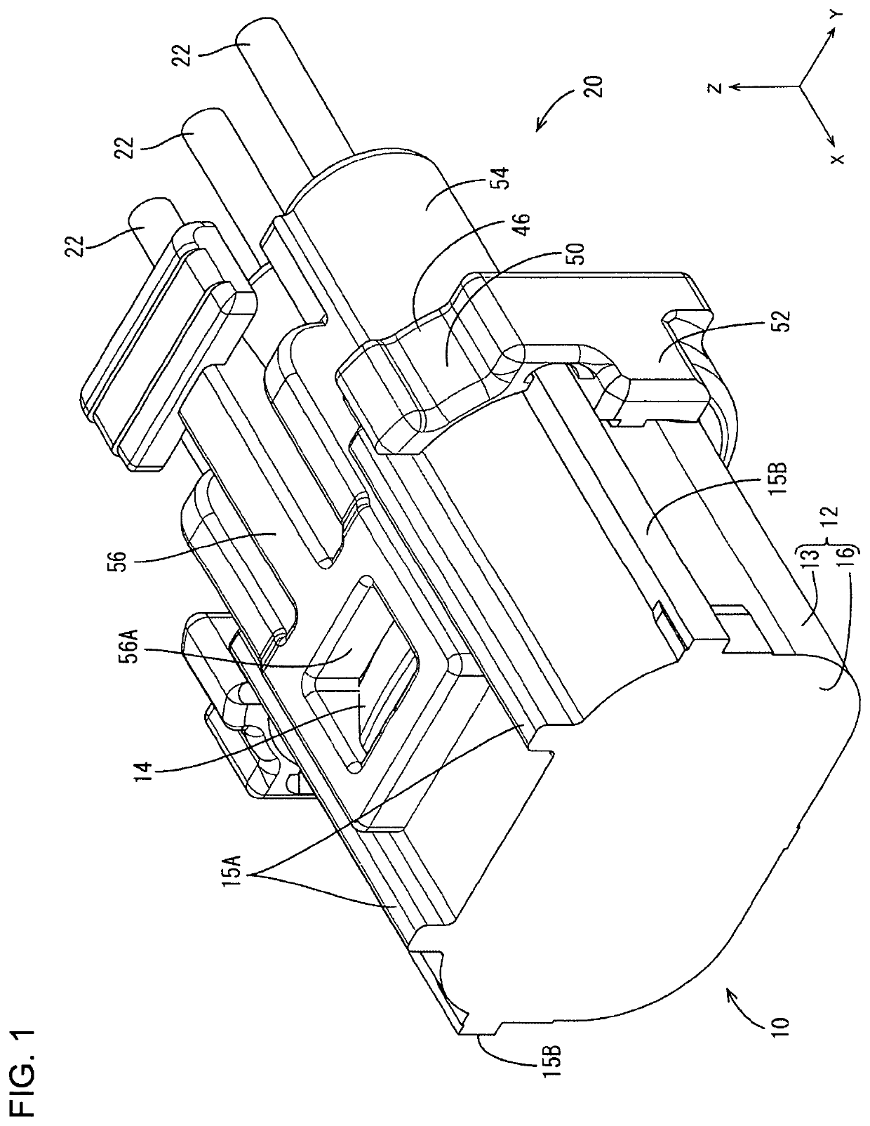
[0029]A connector 20 of this embodiment is a female connector to be connected to a mating male connector 10 and, for example, is arranged in a power supply path of a vehicle, such as an automotive vehicle. In the following description, an X direction, a Y direction and a Z direction of FIG. 1 are referred to as a forward direction, a leftward direction and an upward direction.

[0030](Male Connector 10)

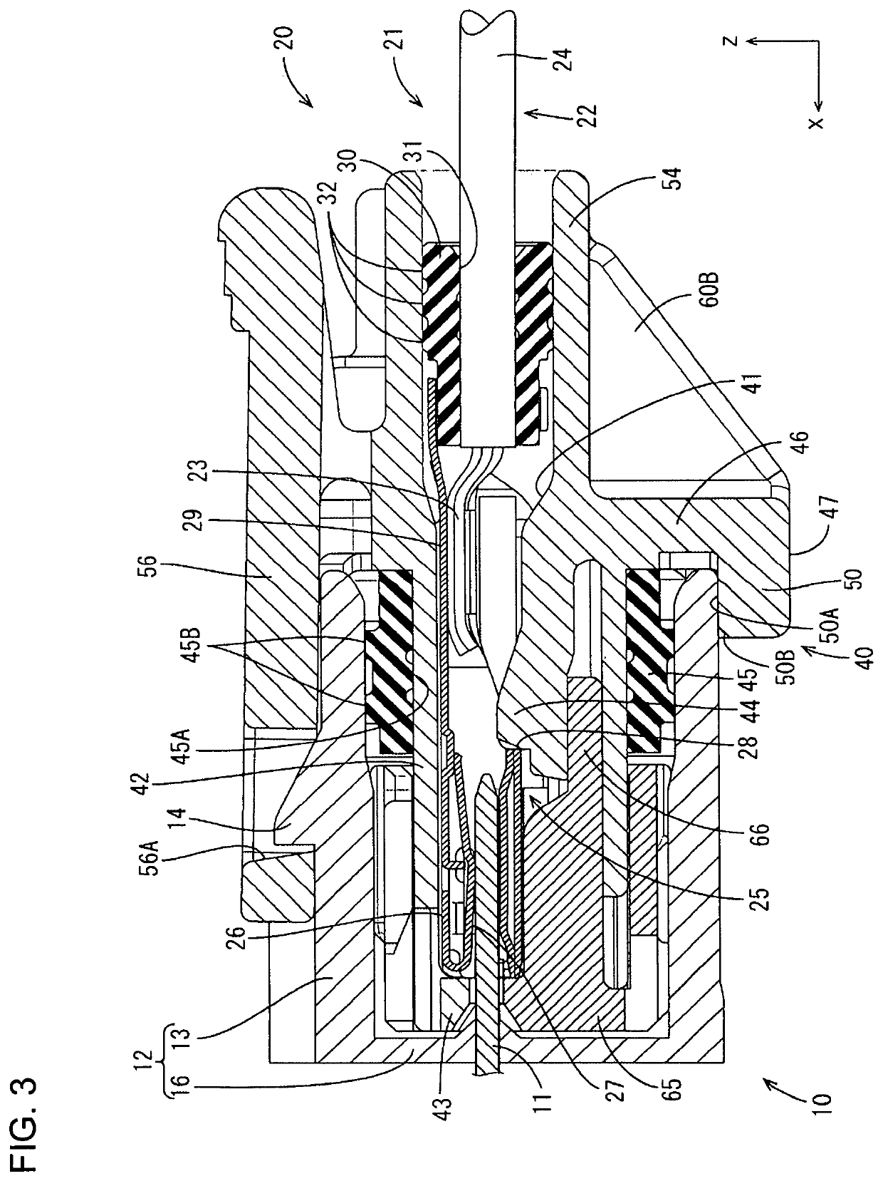
[0031]As shown in FIG. 3, the male connector 10 includes male terminals 11 (front ends of the male terminals 11 are not shown in FIGS. 1 to 3) and a male housing 12 made of insulating synthetic resin for holding the male terminals 11. The male housing 12 includes an open receptacle 13 and a back wall 16 closing the receptacle 13. The male terminals 11 penetrate through the back wall 16 to project into the receptacle 13, and the unillustrated front ends may be bent into an L shape.

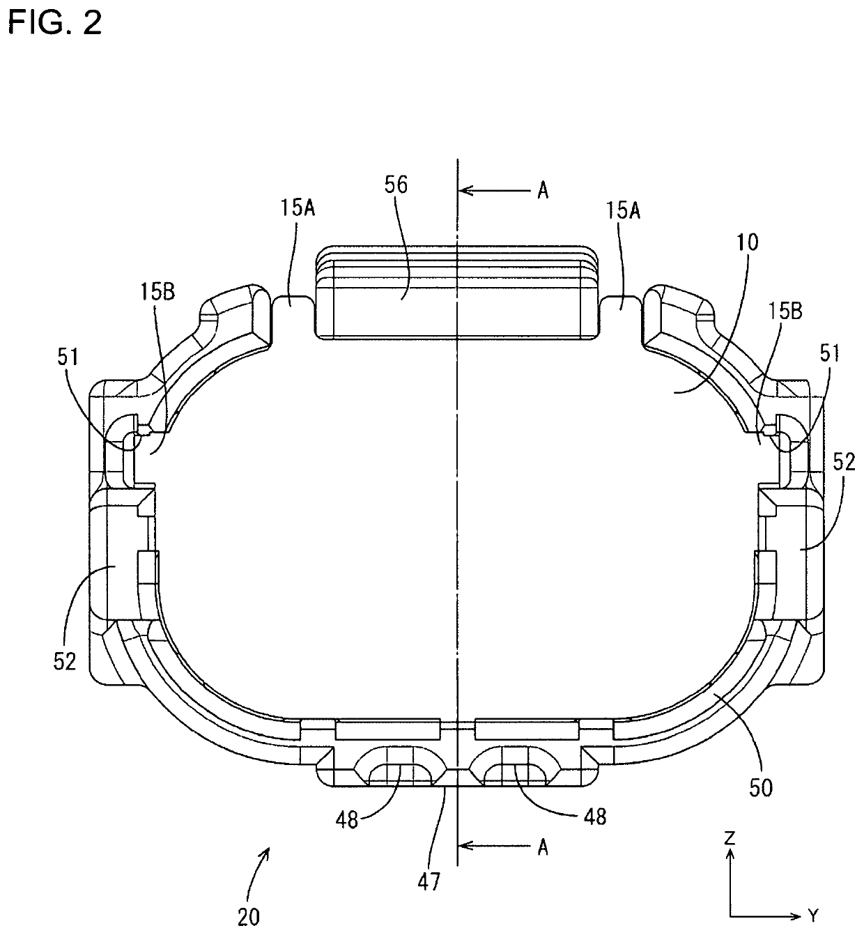
[0032]The receptacle 13 is an elliptical tu...


PUM


Abstract

A connector 20 to be fit into an open receptacle 13 of a male connector 10 includes a terminal 25 connected to an end part of a wire 22, and a housing 40 for holding the terminal 25. The housing 40 includes a lead-out portion 54 for leading out the wire 22 connected to the terminal 25 to outside, a protruding portion 46 protruding outward to face a tip part of the receptacle 13, an external fitting portion 50 projecting from the protruding portion 46 toward the receptacle 13 to be externally fit to the tip part of the receptacle 13 and expose an outer surface of a base end side of the receptacle 13, and a reinforcing rib 60A, 60B connected to the lead-out portion 54 and the protruding portion 46.

Description

BACKGROUNDField of the Invention[0001]A connector is disclosed in this specification.Related Art[0002]Japanese Unexamined Patent Publication No. 2008-166046 discloses a connector that includes a female housing and a male housing to be connected to each other. A backlash preventing rib is provided on one of an outer peripheral surface of a terminal accommodating portion for accommodating a female terminal in the female housing and an inner peripheral surface of a small receptacle open forward in the male housing. The vibration preventing rib is squeezed between mating peripheral surfaces to suppress vibration between the housings and to suppress terminal wear.[0003]Dimensional accuracy of the backlash preventing rib and the mating peripheral surface needs to be enhanced and creates a problem of increasing manufacturing cost.[0004]This specification was completed on the basis of the above situation and aims to provide a connector capable of suppressing troubles caused by vibration whi...

Claims


Application Information

Patent Timeline
Patent Type & Authority Patents(United States)
IPC IPC(8): H01R13/52H01R13/502H01R13/627H01R13/42
CPCH01R13/502H01R13/5221H01R13/6272H01R13/42H01R2201/26H01R13/516H01R13/533H01R13/4223
Inventor MASUDA, TAKESHIOOTANI, HIROMUTERESAWA, TAKEHIDEHASHIMOTO, YOUJIROUNAKAI, KAZUO
Owner AUTONETWORKS TECH LTD
Why Eureka
Try Eureka