Transformer structure

a transformer and structure technology, applied in the field of transformers, can solve the problems of high cost of multi-layer printed circuit boards, and achieve the effects of low cost, high frequency, and low cost of manufacturing

Inactive Publication Date: 2005-03-15
ENTRUST POWER CO LTD
View PDF5 Cites 166 Cited by
  • Summary
  • Abstract
  • Description
  • Claims
  • Application Information

AI Technical Summary

Benefits of technology

Another purpose of the present invention is to provide a transformer structure that is inexpensive to manufacture.
A further purpose of the present invention is to provide a high frequency transformer structure that is inexpensive to manufacture.
The preferred embodiment of the present invention relates to a planar transformer comprising a plurality of juxtaposed magnetic cores as well as a two-layer p

Problems solved by technology

This kind of multi-layers printe

Method used


Image

  • Transformer structure
  • Transformer structure
  • Transformer structure

Examples


first embodiment

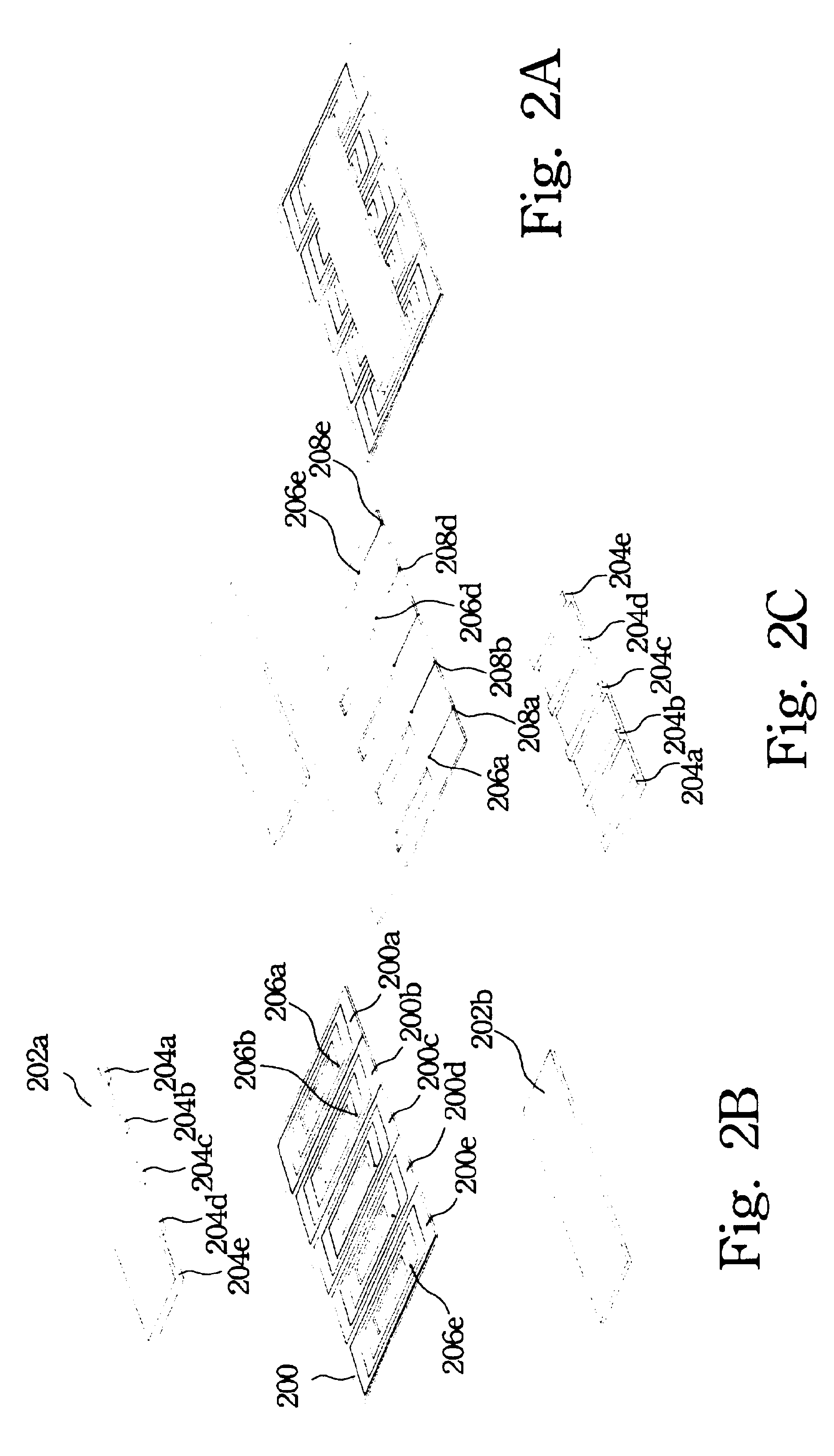
FIGS. 2A to 2C show the first preferred embodiment of the present invention. FIG. 2A is the top view in accordance with a planar transformer and relates to a planar transformer comprising a core with five juxtaposed arms as well as a two-layer printed circuit board for spiraling a plurality of windings. It is noted that the plurality of windings may be also built in different two-layer printed circuit board. Each arm of the core respectively goes through a corresponding hole in the middle of these windings, to magnetically couple the current in the main winding to the other windings.

FIG. 2B shows an exploded top view in accordance with the first embodiment of a planar transformer. A selected number of windings is shown in FIG. 2B, but anyone skilled in the art will understand that the number of the windings of the transformer is changeable. The elements of the transformer described in the FIG. 2B are: five juxtaposed windings 200a to 200e formed over a two-layer printed circuit boar...

second embodiment

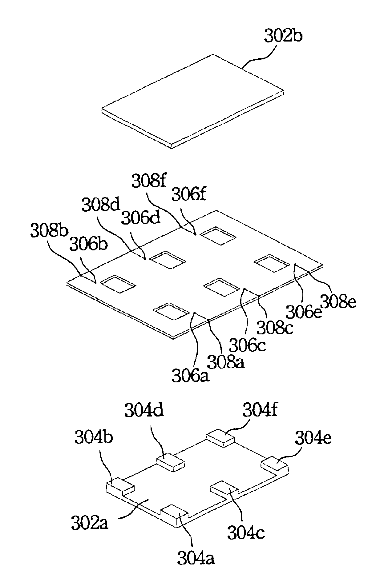
FIGS. 3A to 3C show the second preferred embodiment of the present invention. FIG. 3A is the top view in accordance with a planar transformer. It relates to a planar transformer comprising a core with six arms as well as a two-layer printed circuit board in which six windings are spiraled. Each arm of the core respectively goes through a corresponding hole in the middle of these windings, to magnetically couple the current in the main winding to the other windings.

FIG. 3B shows an exploded top view in accordance with the second embodiment of a planar transformer. The elements of the transformer described in the FIG. 3B are: six windings 300a to 300f formed over a two-layer printed circuit board 300 and six arms ferrite core members 302a and 302b. Similarly, the six windings 300a to 300f can have spiralling conductor traces or some other wiring pattern. In this embodiment, six windings 300a to 300f are wired in a spiral trace.

Each arm of the ferrite core goes through the correspondin...


PUM


Abstract

The present invention describes a planar transformer having a plurality of juxtaposed magnetic cores as well as a two-layer printed circuit board for spiralling a plurality of windings. Each arm of a plurality of juxtaposed magnetic cores respectively goes through a corresponding hole in the middle of these windings, to magnetically couple the current in the main winding to the other windings.

Description

FIELD OF THE INVENTIONThe present invention relates to a transformer, and more specifically, to a structure of a planar transformer.BACKGROUND OF THE INVENTIONTransformers are necessary in many types of electrical apparatus.A basic transformer comprises primary coils, secondary coils and a core. The coils are made, for example, of copper wire. They may be arranged so as to be juxtaposed. Alternatively, they may be arranged so that one coil surrounds another coil. A coil has one or more windings. As a result of the ongoing reduction in size of electrical apparatus, transformers manufactured also comprise coils having smaller dimensions. Said coils may be made, for example, from a number of layers of an insulating material on which winding portions of the coils are provided. A transformer of this type is referred to as a multilayer or planar transformer.FIG. 1A is the top view of a conventional planar transformer. FIG. 1B shows an exploded top view of the conventional planar transform...

Claims


Application Information

Patent Timeline
IPC IPC(8): H01F27/28H01F17/00
CPCH01F27/2804H01F17/0013
Inventor YANG, LEE-LUNG
Owner ENTRUST POWER CO LTD
Why Eureka
Try Eureka