Inductive position sensor

A sensor and inductive technology, applied in the direction of converting sensor output, using electric/magnetic devices to transfer sensing components, instruments, etc., to achieve the effect of reducing measurement distortion

Active Publication Date: 2008-03-19
MELIUS
View PDF3 Cites 15 Cited by
  • Summary
  • Abstract
  • Description
  • Claims
  • Application Information

AI Technical Summary

Problems solved by technology

Therefore, even if some direct coupling remains between the separate meander windings, this winding configuration is not as sensitive to uneven direct coupling as the first embodiment

Method used


Image

  • Inductive position sensor
  • Inductive position sensor

Examples


Embodiment Construction

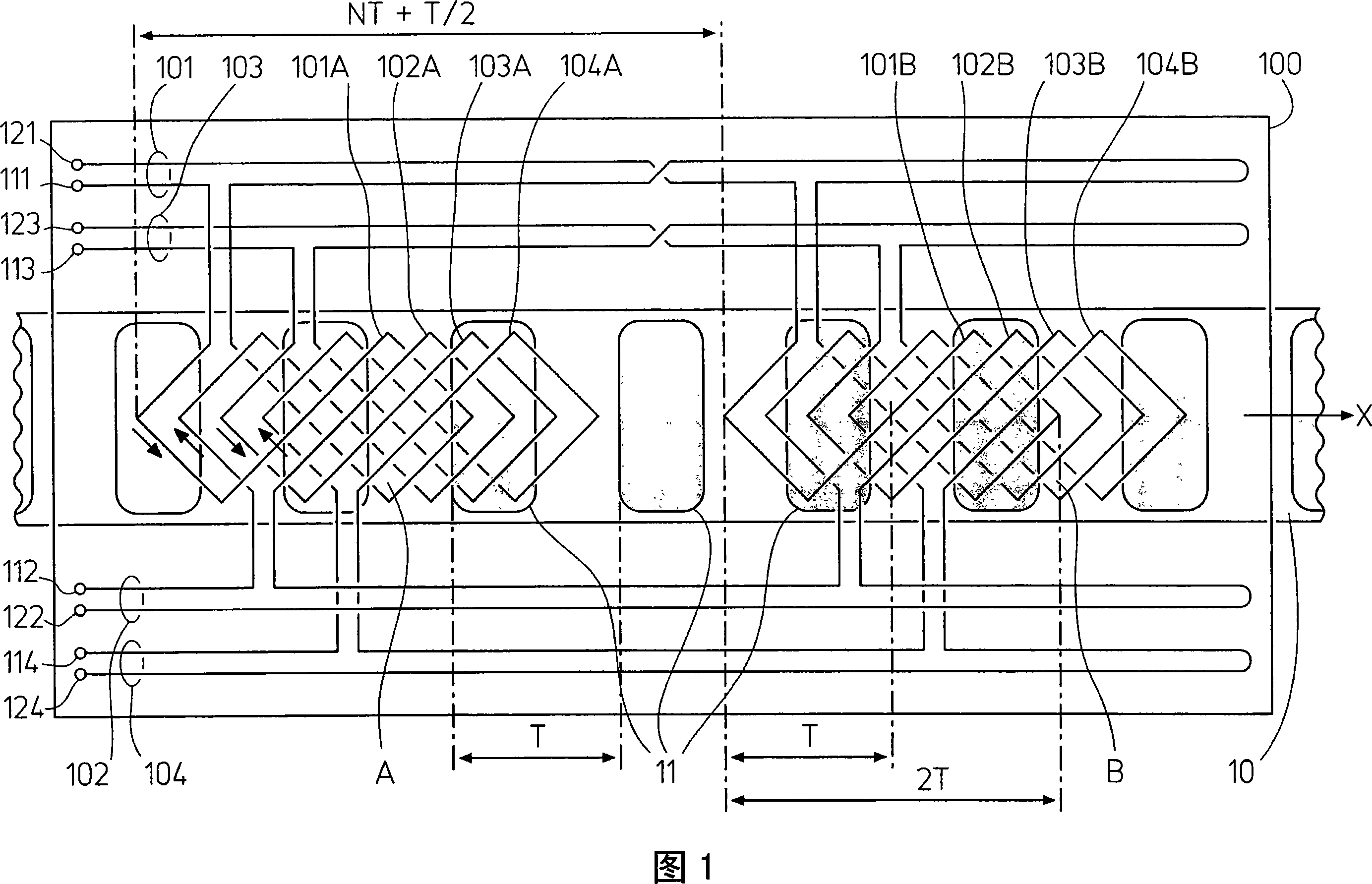
[0016] A first embodiment of a sensor according to the invention is shown in FIG. 1 . The sensor comprises a relatively movable flat scale 10 along a path x, beneath a flat read head 100 with four windings 101, 102, 103, 104 shown in perspective, since the four windings are at or close to The side facing the scale, ie below the readhead 100 when viewed from above. The scale 10 has a spatially periodic sequence of conductive screens 11 having a spatial period T along the path x (ie in the direction of the scale).

[0017] Each winding 101 , 102 , 103 , 104 is divided into two separate identical winding elements facing scale 10 , 101A and 101B, 102A and 102B, 103A and 103B, 104A and 104B respectively. The winding elements 101A, 102A, 103A, 104A displaced from each other by T / 4 are interwoven together in the first winding element pattern A, and the winding elements 101B, 102B, 103B, 104B displaced from each other by T / 4 are interwoven with the first winding element The same sec...


PUM


Abstract

An inductive position sensor has a spatially periodic scale with a series of conducting or permeable features of pitch T and a reading head with drive windings and sense windings, facing the scale with a spatial period 2T along the scale. The windings are each divided in two identical winding elements having the same relative location within two identical winding element patterns having a center-to-center distance along the scale of NT+T / 2, N being an integer, and connected so that the winding element polarities in each winding are either opposed for drive windings and the same for sense windings or the same for drive windings and opposed for sense windings. Thereby, direct couplings in both patterns cancel each other, while the spatially periodic signals coupled via the scale reinforce each other.

Description

technical field [0001] The present invention relates to an inductive position sensor, and more particularly to an inductive position sensor with a relatively movable scale and a read head, the scale includes a spatially periodic conductive or magnetically permeable feature sequence with a space period of T, and the read head Scale-facing drive and sense windings are included with a spatially periodic configuration along the scale with a spatial period of 2T. Background technique [0002] In such sensors, the signal coupled from one winding to the other through the spatial periodicity of the scale characteristic varies sinusoidally along the scale with readhead position with a spatial period equal to the spatial period T of the scale. By measuring two or more of these signals, two or more mutually displaced sinusoidal functions are obtained from which the position of the readhead along the scale can be determined. This sensor is simple, rough, and small in size. Because its...

Claims


Application Information

Patent Timeline
Patent Type & Authority Applications(China)
IPC IPC(8): G01D5/20
CPCG01D5/202
Inventor 汉斯·乌尔里希·迈尔
Owner MELIUS
Why Eureka
Try Eureka