Resonant frequency tracking circuit

A technology of tracking circuit and resonant frequency, applied in the direction of electrical components, automatic power control, etc., can solve problems such as inability to eliminate resonant frequency offset of LC parameters, inability to overcome resonant frequency offset, poor product consistency, etc., to save device screening time, improving energy conversion efficiency, and reducing self-loss

Active Publication Date: 2013-11-27
CRM ICBG (WUXI) CO LTD
View PDF6 Cites 16 Cited by
  • Summary
  • Abstract
  • Description
  • Claims
  • Application Information

AI Technical Summary

Problems solved by technology

[0007] The purpose of the present invention is to provide a resonant frequency tracking circuit, which is used to solve the problem of high production cost, poor production efficiency, poor product consistency, inability to overcome the resonant frequency shift caused by load changes, and the circuit board of the existing wireless charger. The resonant frequency shift caused by the parasitic reactance above can not eliminate the problem of the resonant frequency shift caused by the change of LC parameters with temperature

Method used


Image

  • Resonant frequency tracking circuit
  • Resonant frequency tracking circuit
  • Resonant frequency tracking circuit

Examples


Embodiment Construction

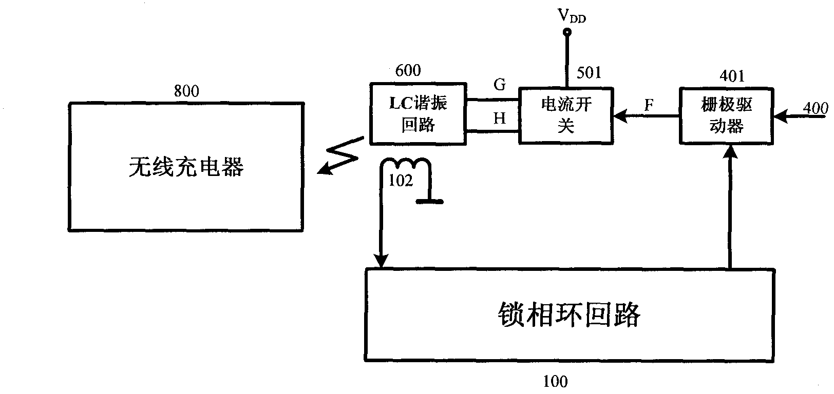
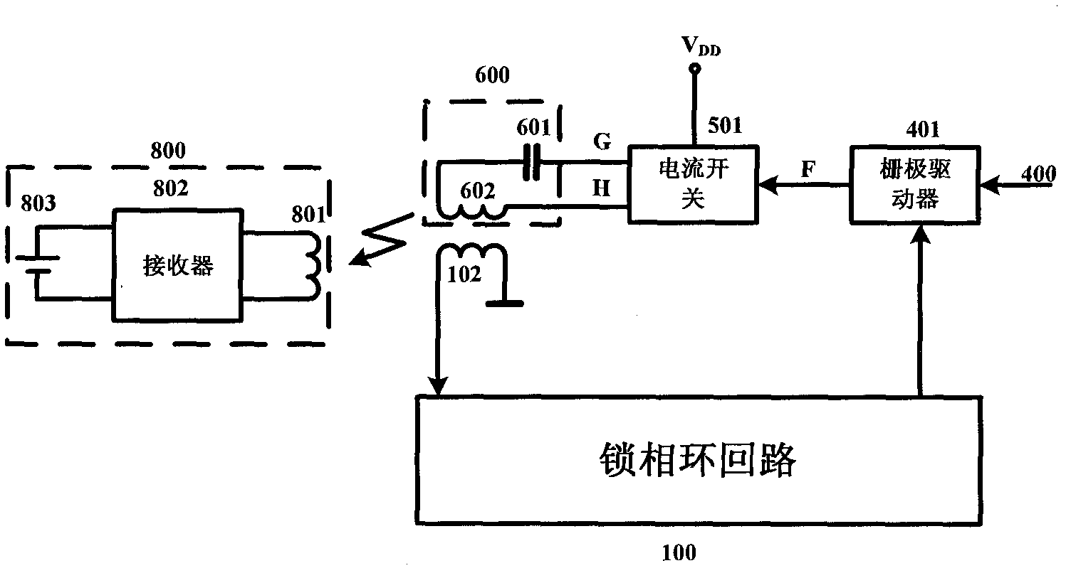
[0037] figure 1 It is a schematic diagram of the resonant frequency tracking circuit of the present invention, as figure 1 As shown, the structure of the resonant frequency tracking circuit according to an embodiment of the present invention is: the output terminal of the current switch 501 is connected to the LC resonant circuit 600, and the detection inductance 102 with one end grounded is coupled with the LC resonant circuit 600 by mutual inductance; a phase-locked loop The circuit 100 is connected to the other end of the detection inductor 102; a wireless charger 800 is coupled to the LC resonant tank.

[0038] The current switch 501 is used to convert the DC voltage input by the power supply into a high-frequency pulse current, and convert the high-frequency pulse current into electromagnetic field energy through the LC resonant circuit 600 and transmit it to the wireless charger 800; the detection inductance 102 is used to obtain the LC resonant circuit 600 frequency an...


PUM


Abstract

The invention discloses a resonant frequency tracking circuit. The resonant frequency tracking circuit comprises a current switch for converting direct voltage inputted by a power supply into a high-frequency pulse current; an LC resonant circuit connected to an output end of the current switch and used for converting electric energy into electromagnetic energy and then transmitting the electromagnetic energy to a wireless charger; a detection inductor connected to the ground at an end and used for obtaining frequency and phase information of the LC resonant circuit; and a phase locked loop circuit connected to the other end of the detection inductor and used for correcting the frequency and phase information and then outputting the frequency and phase information to the current switch as a feedback signal so as to control pulse current frequency outputted by the current switch. According to the invention, the inductive wireless charger LC resonant frequency automatic tracking device reduces the required accuracy of LC parameters from 1% to 10%, and therefore production costs are reduced, device screening time is saved and production efficiency is improved.

Description

technical field [0001] The invention relates to a resonant frequency tracking circuit, in particular to a resonant frequency tracking circuit for a charger circuit. Background technique [0002] The inductive wireless charger transmits energy through the electromagnetic wave transmitting coil. In order to ensure efficient energy transmission, the electromagnetic wave transmitting coil must work in a resonant state. [0003] One way to ensure the accuracy of the resonant frequency is to use high-precision instruments to manually screen devices with basically the same parameters from the existing commercial LC devices, for example, use a precision bridge to select qualified products from the existing commercial LC devices, so that the device parameter values The error is within 1% to ensure that the system resonance frequency error is within 2.5%. This method is often used in laboratory research and small-scale production. Although it is simple and easy to implement, the high...

Claims


Application Information

Patent Timeline
Patent Type & Authority Applications(China)
IPC IPC(8): H03L7/087H03L7/099
Inventor 王新成王立龙
Owner CRM ICBG (WUXI) CO LTD
Why Eureka
Try Eureka