A kind of steel bar end burr grinding mechanism and using method

A technology of grinding mechanism and steel bars, which is applied to the parts of grinding machine tools, machine tools suitable for grinding the edge of workpieces, grinding machines, etc., can solve problems such as large errors, achieve short grinding time, constant grinding effect, and uniform propulsion force Effect

Active Publication Date: 2021-07-20
陕西勇拓机械科技有限公司
View PDF11 Cites 0 Cited by
  • Summary
  • Abstract
  • Description
  • Claims
  • Application Information

AI Technical Summary

Problems solved by technology

[0004] The purpose of the present invention is to provide a mechanism for grinding the burr at the end of steel bar and its use method, so as to solve the problem of large error in the prior art

Method used


Image

  • A kind of steel bar end burr grinding mechanism and using method
  • A kind of steel bar end burr grinding mechanism and using method
  • A kind of steel bar end burr grinding mechanism and using method

Examples


Embodiment 1

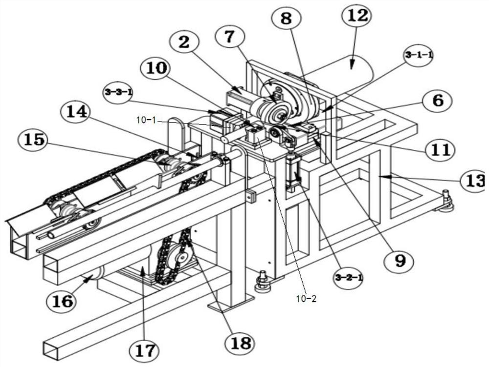
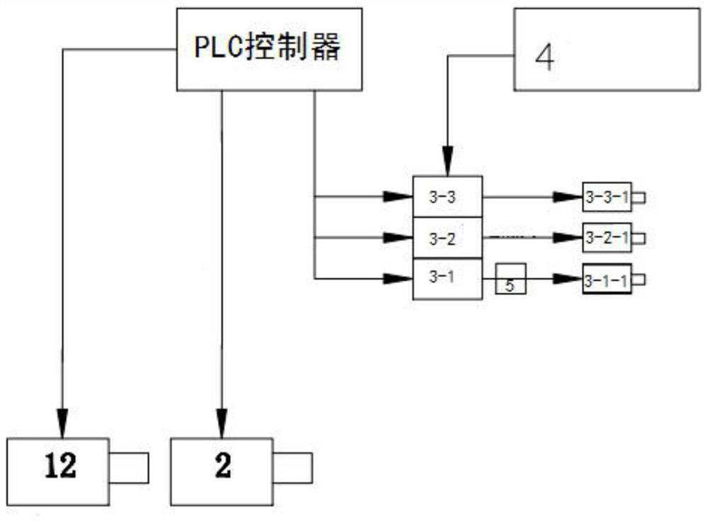
[0025] Such as figure 1 with figure 2 As shown, a reinforcing mechanism includes a grinding mechanism and a steel transport mechanism including an eccentric rotating mechanism 8 and a rack 13, and an eccentric rotating mechanism 8 is connected to a eccentric rotary motor having a driving eccentric rotating mechanism 8. 12, the eccentric rotating mechanism 8 is connected to the second motor 2, the second motor 2 output shaft is connected to the grinding wheel 7, and the eccentric rotating mechanism 8 is connected to the rack 13, and the rack 13 is also connected to a PLC controller, a PLC controller. Connect to the second motor 2 electrical signal, the steel transport mechanism is connected to the front of the frame 13 for transporting the steel bar to the grinding wheel 7, wherein the reinforcing mechanism is also attached to the sensor 14, and the sensor 14 is connected to the PLC controller electrical signal. A clamping mechanism 10 is also connected to the rack 13 in front of t...

Embodiment 2

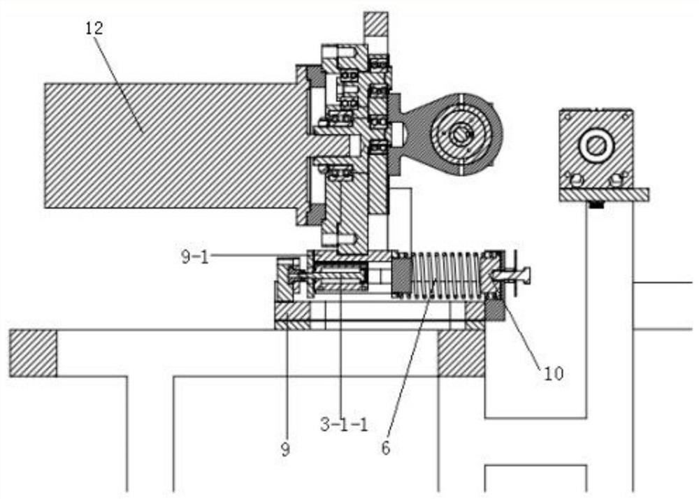
[0030] Such as figure 1 with figure 2 As shown, on the basis of the first embodiment, the eccentric rotating mechanism 8 is connected to the slider 9-1, and the frame 13 is connected to the frame 13, and the slider 9-1 is mounted in the first guide slide. On the rail 9, there is also a first cylinder 3-1-1 in the slider 9-1, and the first cylinder 3-1-1 rear end is connected to the baffle of the first guide slide 9, the first cylinder 3- 1-1 Connect the air compressor 4 through the pipe, the first solenoid valve 3-1 and the air pressure adjustment table 5, the first solenoid valve, and the first solenoid valve are connected to the conduit between the first cylinders 3-1-1 and the air compressor 4. 3-1 and Air Pressure Adjustment Table 5 are connected to the PLC controller electrical signal.

[0031] Such as image 3As shown, the eccentric rotating mechanism 8 is connected to the slider 9-1, and the first guide slide rail 9 is connected, and the first guide rail 9 is connected to th...

Embodiment 3

[0037] Such as figure 1 with figure 2 As shown, on the basis of Example 2, the clamping mechanism includes a first fixing block 10-1 and a second fixing block 10-2, and the first fixed block 10-1 is connected to the rack 13, and the second fixation is Block 10-2 is connected to the frame 13 by the second sliding guide, and the first fixed block 10-1 and the second fixed block 10-2 are left out, and the second fixed block 10-2 is away from the first fixed block. On one side of 10-1 is also connected with a third cylinder 3-3-1 for pushing the second fixing block 10-2 on the second sliding guide rail, the third cylinder 3-3-1 is connected to the rack 13, Moreover, the third cylinder 3-3-1 is connected to the pipeline 4, and the third cylinder 3-3-1 and the tube between the third cylinders 3-3-1 and the air compressor 4 are connected to the third solenoid valve 3-3, the third solenoid valve. 3-3 Connect to the PLC controller electrical signal.

[0038] The first fixing block 10-1 is ...


PUM


Abstract

The invention discloses a grinding mechanism for the burr at the end of steel bars and a use method thereof, comprising a grinding mechanism and a steel bar transport mechanism. The grinding mechanism includes an eccentric rotation mechanism and a frame, and an eccentric rotation motor driving the eccentric rotation mechanism is connected behind the eccentric rotation mechanism , the front of the eccentric rotation mechanism is connected with a second motor, the output shaft of the second motor is connected with a grinding wheel, the eccentric rotation mechanism is connected to the frame, and a PLC controller is also connected to the frame, and the PLC controller is connected to the second motor with electrical signals, The steel bar transport mechanism is connected to the front of the frame for transporting the steel bar to the direction of the grinding wheel, wherein a sensor is also installed on the steel bar transport mechanism, and the sensor is connected with the PLC controller for electrical signals. According to the fact that when the rotating grinding wheel touches the end face of the steel bar, the working current of the second motor will increase instantaneously. Write the current value at this time into the PLC controller as the starting point of grinding. The diameter of the grinding wheel will become smaller. No need to make any parameters and adjustments, it can still be normal work, and the sanding effect remains the same.

Description

Technical field [0001] The present invention relates to the field of end burr grinding techniques after the steel bonding, and more particularly to a reinforced terminal burr grinding mechanism and method of use. Background technique [0002] Disadvantages of the control principle of rear end burr grinding mechanism after domestic reinforced steel bracket: (Example) First type (grinding wheel stripping): 1. The grinding wheel is fixed, the motor drives the grinding wheel, the reinforcement of the feed cell The reinforcement is conveyed to the high-speed rotating grinding wheel by the motor drive feed roller, and the steel bar is contacted with high-speed rotating grinding wheels through the roller. It has a disadvantage: 1. The promotion is not good to master, the grinding wheel is easy to fry, there is a large safety hazard. 2. Due to the structural restriction reinforcing, the position is not constrained, so the state of the steel bars is unconstrained, and the steel state will...

Claims


Application Information

Patent Timeline
Patent Type & Authority Patents(China)
IPC IPC(8): B24B9/04B24B41/00B24B41/06B24B47/22B24B51/00
CPCB24B9/04B24B41/005B24B41/007B24B41/067B24B47/22B24B51/00
Inventor 姜勇
Owner 陕西勇拓机械科技有限公司
Why Eureka
Try Eureka