Variable-nozzle mechanism, exhaust turbocharger equipped therewith, and method of manufacturing exhaust turbocharger with the variable-nozzle mechanism

a variable nozzle and nozzle mechanism technology, which is applied in the direction of machines/engines, liquid fuel engines, forging/pressing/hammering apparatuses, etc., can solve the problems of variable nozzle mechanism breakage, poor engine performance, sliding or rolling contact parts are liable to wear, etc., to achieve simple and easy mounting and dismounting of the variable nozzle mechanism, easy adjustment and accurate

Active Publication Date: 2008-07-08
MITSUBISHI HEAVY IND ENGINE & TURBOCHARGER LTD
View PDF14 Cites 32 Cited by
  • Summary
  • Abstract
  • Description
  • Claims
  • Application Information

AI Technical Summary

Benefits of technology

[0018]In light of the problems mentioned above, the first objective of the present invention is to provide an exhaust turbocharger of variable turbine capacity in which the occurrence of eccentric motion or running away of the same due to excessive wear of the supporting part of the same and the occurrence of reduction in engine performance due to malfunction of the variable-nozzle mechanism caused by the eccentric motion or running away, or breakage of the variable-nozzle mechanism, can be prevented.
[0019]The second objective of the present invention is to provide an exhaust turbocharger of variable turbine capacity which demands decreased working-hours by easing the mounting and dismounting of variable-nozzle mechanism, can improve reliability by eliminating the dropping-off of some of the constituent elements when assembling, and can improve maintainability by easing the supplying and replacing of variable-nozzle mechanism as an assembled unit.
[0020]The third objective of the present invention is to provide an exhaust turbocharger of variable turbine capacity in which the turbine casing can be of one piece article, the clearance adjustment of thrust bearing part of variable-nozzle mechanism is eased, and the number of parts and assembling man-hours are reduced.

Problems solved by technology

Therefore, the sliding or rolling contact parts are liable to wear.
Excessive wear of those parts induces an error in the relation of the actuator output and nozzle vane opening resulting in poor engine performance and sometimes breakage of the variable-nozzle mechanism.
Accordingly, the mounting and dismounting of the variable-nozzle mechanism to the exhaust turbocharger is a time-consuming work in this prior art.
Besides, there is a danger of dropping out of the spacers and dowel pins when dismounting the variable-nozzle mechanism, which may cause harm to the turbine.
Therefore, it is impossible to supply and replace the variable-nozzle mechanism as an assembled unit, and the replacement of the constituent elements of the turbocharger is not easy resulting in poor maintainability.
However, with prior art 4, since the drive ring connection part of the variable-nozzle mechanism is covered with the additional gas outlet casing provided apart from the turbine casing and the front end face of the gas outlet casing is used to bear the thrust force toward the gas outlet side by allowing the rear face of the inner ring part of the nozzle mount to contact the inner front face of the gas outlet casing, it is necessary to provide the gas outlet casing apart from the turbine casing, resulting in increased number of parts and increased man-hours of assembling.

Method used


Image

  • Variable-nozzle mechanism, exhaust turbocharger equipped therewith, and method of manufacturing exhaust turbocharger with the variable-nozzle mechanism
  • Variable-nozzle mechanism, exhaust turbocharger equipped therewith, and method of manufacturing exhaust turbocharger with the variable-nozzle mechanism
  • Variable-nozzle mechanism, exhaust turbocharger equipped therewith, and method of manufacturing exhaust turbocharger with the variable-nozzle mechanism

Examples


first embodiment

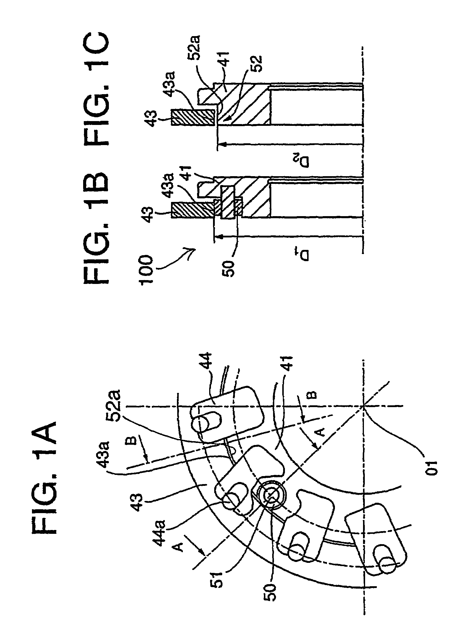
[0066]Referring to FIG. 1A˜FIG. 1C showing the variable-nozzle mechanism 100 according to the present invention, reference numeral 41 is the nozzle mount, 43 is the drive ring, 44 are the lever plates for connecting the drive ring 43 and nozzle vanes 40, 44a are pins for connecting the drive ring 43 to the lever plates 44.

[0067]A plurality of roller pins 51 are located circumferentially and fixed to the nozzle mount 41, a roller 50 being supported for rotation on each of the roller pins 51. The drive ring 43 is supported for rotation on the nozzle mount 41 on the peripheral part thereof via the rollers 50.

[0068]In this first embodiment of the variable-nozzle mechanism 100, in addition to the inner circumference face 43a of the drive ring 43 being supported by the rollers in rolling contact as can be seen in FIG. 1A and FIG. 1B, the second supporting face 52a is provided on the peripheral part 52 of the drive ring on the portion where the rollers 50 are not attached as can be seen in...

second embodiment

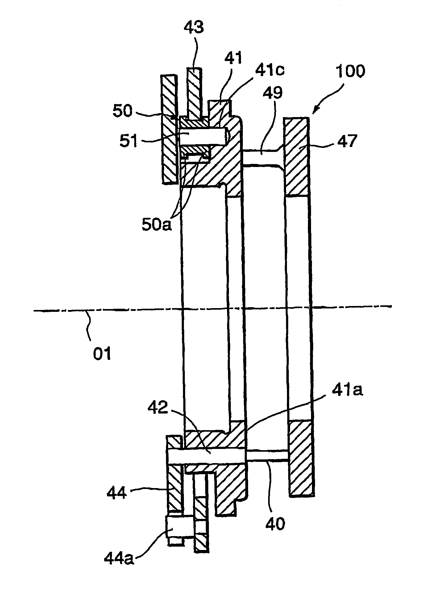
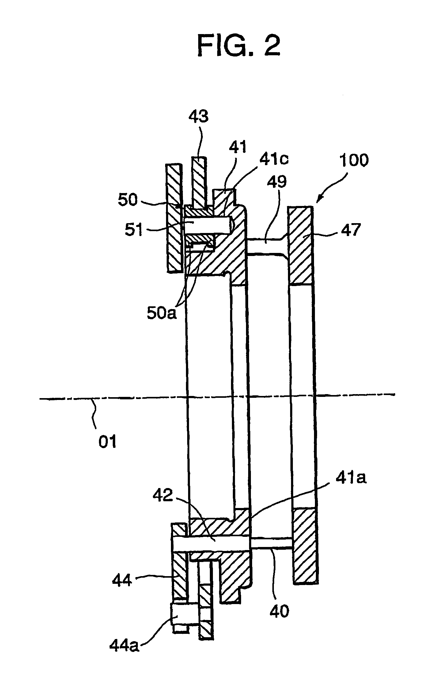
[0072]Referring to FIG. 2 showing the variable-nozzle mechanism 100 according to the present invention, reference numeral 41 is the nozzle mount formed in an annular shape, 40 are a plurality the nozzle vanes located circumferentially equally spaced, each nozzle vane 40 being fixed to the nozzle pin 42 which is fitted to the nozzle mount and rotatable to vary the angle of blade of the nozzle vane. Reference numeral 47 is the nozzle plate of annular plate shape and is connected to the nozzle mount 41 with a plurality of nozzle supports 49 circumferentially located and fixed to the rear side (gas passage side, right side in the drawing) of the nozzle mount 41.

[0073]Reference numeral 43 is the drive ring supported on the peripheral part of the nozzle mount 41 formed in an annular shape, the drive ring being rotatable there. Reference numeral 51 are the roller pins, each of the pins 51 being pressed in to be fixed in each of a plurality of holes 41c drilled in the front side (bearing ho...

third embodiment

[0090]the exhaust turbocharger with the variable-nozzle mechanism 100 is shown in FIG. 5A and FIG. 5B.

[0091]In this embodiment, spot faces 41a are formed around the holes 41c in the nozzle mount 41 for washers 52 to be seated between the spot faces and the rollers 50. The sliding clearance of the roller 50 in axial direction can be adjusted by the thickness of the washer, so that the accuracy of the elements contacting the roller in axial direction is not required severely resulting in cost reduction in machining.

[0092]When the sliding faces contacting the rollers 50 wear excessively, it is enough to replace the washers without replacing other components such as nozzle mount 41, rollers 50, and bosses 20. Therefore, maintenance cost can be reduced.

[0093]Other than that mentioned above, the embodiment shown in FIG. 5A and FIG. 5B is the same as the embodiment shown in FIG. 3 and the similar constituent elements are denoted by the same reference numerals as those of FIG. 3.


PUM

PropertyMeasurementUnit
angleaaaaaaaaaa
actuating forceaaaaaaaaaa
flow rateaaaaaaaaaa

Abstract

An exhaust turbocharger with a variable-nozzle mechanism with fail-safe feature included is provided with which, even if wear of the drive ring supporting part where the supporting elements are in reciprocating sliding or rolling contact with each other under high temperature without lubrication increases, the drive ring can be supported on the nozzle mount on the second supporting part, which enables the drive ring to be always supported rightly on the nozzle mount, and to prevent the occurrence of eccentric rotation or dropping out of the drive ring due to excessive wear of the drive ring supporting part or the occurrence of reduction in engine performance due to malfunctions of the variable-nozzle mechanism such as the error in the relation between the output of the actuator and the nozzle vane opening or the occurrence of breakage of the variable-nozzle mechanism as has been experienced in prior arts.

Description

FIELD OF THE INVENTION[0001]The present invention relates to a variable-nozzle mechanism of turbine nozzles which is applied to an exhaust turbocharger of an internal combustion engine for varying the blade angle of nozzle vanes of the exhaust turbocharger through transmitting the actuating force of an actuator to the nozzle vanes via a drive ring, and an exhaust turbocharger with the variable-nozzle mechanism to make the capacity of the turbine variable.PRIOR ART[0002]In these years many turbocharged internal combustion engines adopt variable capacity type turbochargers which can vary the flow rate of the exhaust gas from the engines flowing to the turbines through the scroll passages thereof according to operation conditions of the engines in order to adjust the flow rate of the exhaust gas to match the optimal operation conditions of the turbochargers.[0003]The variable capacity type turbocharger is provided with a variable-nozzle mechanism which can vary the blade angle of nozzl...

Claims


Application Information

Patent Timeline
Patent Type & Authority Patents(United States)
IPC IPC(8): F02D23/00F02B37/24F01D17/16
CPCF01D17/165Y10T29/4932F05D2260/30F05D2220/40F01D17/16F02B37/22F02B37/12
Inventor SHIRAISHI, TAKASHIJINNAI, YASUAKIEBISU, MOTOKI
Owner MITSUBISHI HEAVY IND ENGINE & TURBOCHARGER LTD
Why Eureka
Try Eureka