Lighting device and method of making same

a technology of light-emitting devices and light-emitting materials, which is applied in the manufacture of electrode systems, electric discharge tubes/lamps, light-eating apparatuses, etc., can solve the problems of system loss of energy, reducing performance (intensity) and efficiency, and achieves greater luminescent elements, greater luminescent materials, and greater self-absorption

Active Publication Date: 2008-04-17
CREELED INC
View PDF29 Cites 286 Cited by
  • Summary
  • Abstract
  • Description
  • Claims
  • Application Information

AI Technical Summary

Benefits of technology

[0026] Furthermore, the thicker the luminescent element is, and the greater the luminescent material (e.g., phosphor) content in the luminescent element, the greater the amount of self-absorption that will occur. Self-absorption occurs when light emissions within the packaging layer stay within the packaging layer to excite other lumiphor particles and eventually are

Problems solved by technology

Back-scattered light which is scattered back into the light emitting diode chip itself has a very low probability of coming out of the chip, and hence, such back-scattering results in a system loss of energy.
Self-absorption occurs when lig

Method used


Image

  • Lighting device and method of making same
  • Lighting device and method of making same
  • Lighting device and method of making same

Examples


second embodiment

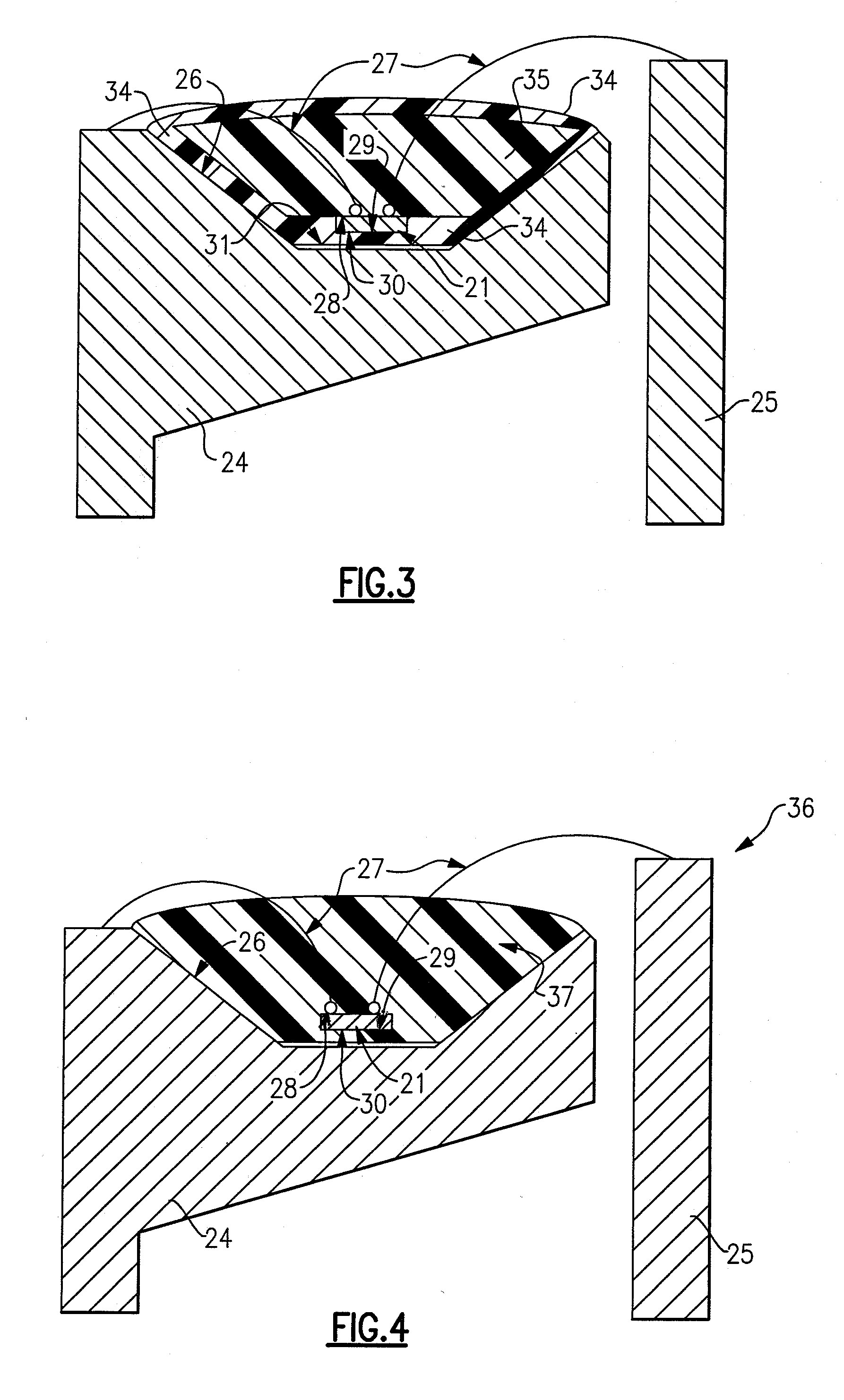
[0193]FIG. 3 is a sectional view of a representative example of a second embodiment according to the present invention. The lighting device 33 depicted in FIG. 3 is similar to the lighting device 20 depicted in FIG. 2, except that: [0194] the shape of the first lumiphor 34 in the device in FIG. 3 differs from the shape of the first lumiphor 22 in the device in FIG. 2; [0195] the shape of the clear fill region 35 in the device in FIG. 3 differs from the shape of the clear fill region 32 in the device in FIG. 2; and [0196] the device in FIG. 3 does not include a second lumiphor (the device in FIG. 2 includes a second lumiphor 23).

[0197] Other elements are similar, and like elements are identified with like reference numbers. Referring to FIG. 3, the first lumiphor 34 surrounds the first LED chip 21. The first LED chip first surface 28 faces a first region of the first lumiphor 34 and the first LED chip second surface 29 faces a second region of the first lumiphor 34.

third embodiment

[0198]FIG. 4 is a sectional view of a representative example of a third embodiment according to the present invention. The lighting device 36 depicted in FIG. 4 is similar to the lighting device 20 depicted in FIG. 2, except that: [0199] the shape of the first lumiphor 37 in the device in FIG. 4 differs from the shape of the first lumiphor 22 in the device in FIG. 2; and [0200] the device in FIG. 4 does not include a second lumiphor (the device in FIG. 2 includes a second lumiphor 23) or a clear fill region (the device in FIG. 2 includes a clear fill region 32).

[0201] Other elements are similar, and like elements are identified with like reference numbers. Referring to FIG. 4, the first lumiphor 37 surrounds the first LED chip 21, which is embedded in the first lumiphor 37. The first LED chip first surface 28 faces a first region of the first lumiphor 37 and the first LED chip second surface 29 faces a second region of the first lumiphor 37.

[0202] Comparative testing was conducted...


PUM


Abstract

A lighting device comprising a light emitter chip, a reflective cup and a lumiphor positioned between the chip and the cup. Also, a lighting device comprising a light emitter chip, a wire bonded to a first surface of the chip and a lumiphor which faces a second surface of the chip. Also, a lighting device comprising a light emitter chip, and a lumiphor, a first surface of the chip facing a first region of the lumiphor, a second surface of the chip facing a second region of the lumiphor. Also, a lighting device comprising a light emitter chip and first and second lumiphors, a first surface of the chip facing the second lumiphor, a second surface of the chip facing the first lumiphor. Also, methods of making lighting devices.

Description

CROSS-REFERENCE TO RELATED APPLICATIONS [0001] This application claims the benefit of U.S. Provisional Patent Application No. 60 / 851,230, filed Oct. 12, 2006, the entirety of which is incorporated herein by reference.FIELD OF THE INVENTION [0002] The present invention is directed to lighting devices which include at least one LED (light emitting diode) chip and at least one lumiphor. The present invention is also directed to methods of making lighting devices which include at least one LED (light emitting diode) chip and at least one lumiphor. BACKGROUND OF THE INVENTION [0003] A large proportion (some estimates are as high as twenty-five percent) of the electricity generated in the United States each year goes to lighting. Accordingly, there is an ongoing need to provide lighting which is more energy-efficient. It is well-known that incandescent light bulbs are very energy-inefficient light sources—about ninety percent of the electricity they consume is released as heat rather than...

Claims


Application Information

Patent Timeline
IPC IPC(8): F21V9/16H01J9/00H01L33/50
CPCH01L33/504H01L33/505H01L33/502H01L33/507H01L33/508H01L33/50H01L2224/48091H01L2224/48247H01L2224/48257H01L2224/45147H01L2924/13091H01L2924/00014H01L2924/00
Inventor NEGLEY, GERALD H.
Owner CREELED INC
Why Eureka
Try Eureka