Vacuum assisted brake system, control method thereof, and vehicle comprising vacuum assisted brake system

A technology of vacuum boost and control method, applied in vehicle parts, transportation and packaging, braking safety system, etc., can solve problems such as hidden safety hazards, inability to stably provide vacuum boost, etc., to extend service life, reduce working time and The number of starts and stops, the effect of ensuring reliability

Active Publication Date: 2010-07-07
BYD CO LTD
View PDF1 Cites 32 Cited by
  • Summary
  • Abstract
  • Description
  • Claims
  • Application Information

AI Technical Summary

Problems solved by technology

[0004] However, the vacuum pump is a vulnerable component, and the frequent braking of the vehicle will accelerate its aging, so it cannot provide vacuum boost stably, thus causing safety hazards

Method used


Image

  • Vacuum assisted brake system, control method thereof, and vehicle comprising vacuum assisted brake system
  • Vacuum assisted brake system, control method thereof, and vehicle comprising vacuum assisted brake system
  • Vacuum assisted brake system, control method thereof, and vehicle comprising vacuum assisted brake system

Examples


Embodiment Construction

[0016] The present invention will be described in detail below with reference to the accompanying drawings.

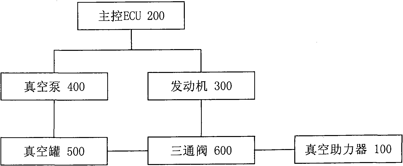
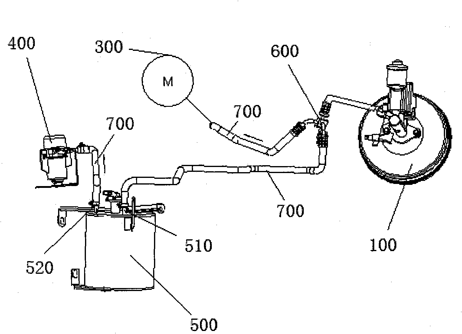
[0017] Such as figure 1 As described above, the present invention provides a brake vacuum booster system, which includes a vacuum booster 100, a vacuum pump 400, a vacuum tank 500, and a main control ECU 200. The vacuum pump 400 passes through the vacuum tank 500 and the vacuum booster 100. The servo air chamber is connected, and the main control ECU200 is electrically connected with the vacuum pump 400, wherein the brake vacuum booster system also includes an engine 300, and the intake manifold of the engine 300 communicates with the vacuum servo air chamber of the vacuum booster 100, The main control ECU 200 provides a vacuum environment for the vacuum booster 100 by controlling the engine 300 and the vacuum pump 400 to be turned on and off so that the engine 300 serves as a main vacuum source and the vacuum pump 400 serves as an auxiliary vacuum source.

[0018] ...


PUM


Abstract

The invention discloses a vacuum assisted brake system, a control method thereof, and a vehicle comprising the vacuum assisted brake system. The vacuum assisted brake system comprises a vacuum booster, a vacuum pump, a vacuum container and a master controller ECU, wherein the vacuum pump is communicated with a vacuum servo air chamber of the vacuum booster by the vacuum container; and the master controller ECU is electrically connected with the vacuum pump. The vacuum assisted brake system also comprises an engine; an intake manifold of the engine is communicated with the vacuum servo air chamber of the vacuum booster; and the master controller ECU makes the engine serve as a main vacuum source and the vacuum pump serve as an auxiliary vacuum source by controlling the opening and closing of the engine and the vacuum pump so as to provide a vacuum environment for the vacuum booster. By using the engine as the main vacuum source, the vacuum assisted brake system of the invention reducesthe operating time and starting/stopping time of the vacuum pump, and avoids frequent opening and long time operation of the vacuum pump, thereby prolonging the service time of the vacuum pump.

Description

technical field [0001] The present invention relates to a brake vacuum booster system and its control method and a vehicle including the system, in particular to a brake vacuum booster system for a hybrid vehicle and its control method and a hybrid vehicle using the brake vacuum booster system . Background technique [0002] At present, cars are basically equipped with brake boosters, especially the use of brake vacuum booster systems is very popular. The principle is to use the pressure difference between the negative pressure generated when the engine is working and the atmospheric pressure to force the rubber diaphragm in the brake vacuum booster to move and push the piston of the brake master cylinder, thereby reducing the force of people stepping on the brake pedal. [0003] In traditional fuel vehicles, the vacuum source of the brake vacuum booster system is provided by the negative pressure generated by the intake manifold when the engine is working. And in existing...

Claims


Application Information

Patent Timeline
Patent Type & Authority Applications(China)
IPC IPC(8): B60T13/52B60T17/22B60K6/20
Inventor 唐振林袁野陈淑君赵兵
Owner BYD CO LTD
Why Eureka
Try Eureka